4
05.01
4.2 Current de–rating
4-88
Siemens AG 2001 All rights reserved
SIMODRIVE 611 Planning Guide (PJU) – 05.01 Edition
4.2 Current de–rating
For MSD/IMM digital and MSD/IMM analog: Sinusoidal current,
current data are RMS values.
1. I
n
continuous current
2. I
s6
current for max. 4 min for S6 duty cycle
3. I
max
Peak current (load duty cycle, refer to Section 4.3)
For FD analog: Square–wave current,
the current values are the amplitude of the square–wave current.
For FD digital: The sinusoidal currents are RMS values.
1. I
n
continuous current
2. I
max
Peak current (load duty cycle, refer to Section 4.3)
Pv
tot
total module power loss
Pv
hose
power loss which can be dissipated through hose cooling
Pv
ext
power loss which can be dissipated through external cooling
Pv
int
power loss which is not dissipated via hose or external cooling
This power loss remains in the cabinet
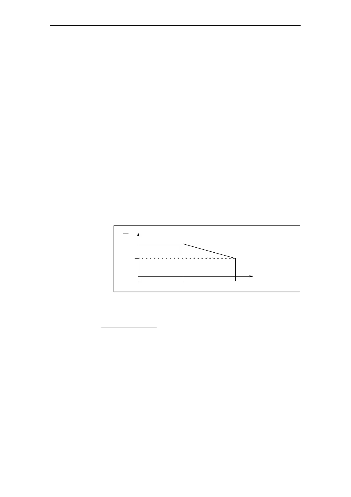
X1 = reduction factor of the current, current de–rating from inverter clock
frequency f
0
of the power transistors (refer to technical data).
I
100 %
X1
In
Ambient temperature up to 40 _C
0 %
f
0
80
f
1
[kHz]
Fig. 4-2 Current de–rating depends on the inverter clock frequency
Formula:
X=100% –
(100 % – X1) (f
T
– f
0
)
8kHz – f
0
x = the reduction factor obtained [in %] for I
n
, I
s6
, I
max
f
T
= selected inverter clock frequency
å In
fT
= x In
f0
/100 %
å Is6
fT
= x Is6
f0
/100 %
å Imax
fT
= x Imax
f0
/100 %
Caution: The currents I
n
, I
s6
and I
max
must be reduced in the same way.
Definition of the
currents
Definition of the
outputs
Current de–rating
depends on the
inverter clock
frequency
4 Power Modules

 Loading...


