9
05.01
9.2 Infeed modules
9-223
Siemens AG 2001 All rights reserved
SIMODRIVE 611 Planning Guide (PJU) – 05.01 Edition
9.2.2 Description of the interfaces and functions
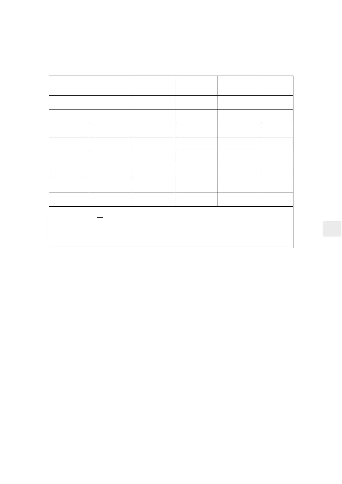
Table 9-1 Overview, infeed modules, internal cooling, commutating reactors, line filter, fuse
Power [KW) Order number Commutating Line filter 1) Line filter Fuse 3) [A]
S1/S6/S
max
reactor only 415 V ! package
only 415 V !
5/6.5/10 UI 6SN1146–1AB0j–
0BA1
2) –
6SN1111–0AA01–
1BA0
– 16
10/13/25 UI 6SN1145–1AA0j–
0AA1
2) –
6SN1111–0AA01–
1AA0
– 25
28/36/50 UI 6SN1145–1AA0j–
0CA0
6SN1111–1AA00–
0CA0
6SN1111–0AA01–
1CA0
– 80
16/21/35 I/R 6SN1145–1BA0j–
0BA1
6SN1111–0AA00–
0BAj
6SN1111–0AA01–
2BAj
6SN1111–0AA01–
2BB0
35
36/47/70 I/R 6SN1145–1BA0j–
0CA1
6SN1111–0AA00–
0CAj
6SN1111–0AA01–
2CAj
6SN1111–0AA01–
2CB0
80
55/71/91 I/R 6SN1145–1BA0j–
0DA1
6SN1111–0AA00–
0DAj
6SN1111–0AA01–
2DAj
6SN1111–0AA01–
2DB0
125
80/104/131 I/R 6SN1145–1BB0j–
0EA1
6SN1111–0AA00–
1EAj
6SN1111–0AA01–
2EAj
6SN1111–0AA01–
2EB0
160
120/156/175 I/R 6SN1145–1BB0j–
0FA1
6SN1111–0AA00–
1FAj
6SN1111–0AA01–
2FAj
6SN1111–0AA01–
2FB0
250
Note:
1) The line filter does not include the commutating reactor! This must be additionally mounted between the line
filter and I/R !
The line filter package comprises a commutating reactor and a line filter, which are separately
combined to form a package.
2) Commutating reactor included in the NE module.
3) Versions NH, D, DO, gL
Switch S1 is provided on the upper side of the NE and monitoring module and
at the front of the UI module 5 kW. It is used to select various functions, refer to
Section 6.1.
FR–
Reference potential for the enable voltage, terminal 9,
floating (connected to the general reference ground terminal 15 via 10 kΩ).
It is not permissible that terminal 19 is connected to terminal 15! (Connect to the
PE rail or X131).
When controlling the enable signals via P–switching electronic outputs (PLC),
terminal 19 should be connected to the 0 V reference potential (ground) of the
external power supply.
The circuit/source must correspond to the requirements of PELV (Protection
Extra Low Voltage) function extra low voltage with protective separation in com-
pliance with EN 60204–1; 6.4.
Switch S1
Terminal 19
9 Important Circuit Information

 Loading...


