5
05.01
5.7 Control module ”SIMODRIVE 611 universal”
5-132
Siemens AG 2001 All rights reserved
SIMODRIVE 611 Planning Guide (PJU) – 05.01 Edition
5.7.2 Description of the terminals and interfaces
The module–specific terminals and interfaces are available together for drive A
and drive B.
Table 5-17 Overview of the module–specific terminals and interfaces
Terminal Function Type Technical data
No. Desig.
1)
Signal terminal, start inhibit (X421)
AS1 Signal contact, start in-
hibit
NC Connector type: 2–pin plug connector
Max. conductor cross–section: 2.5 mm
2
AS2
X421
Checkback signal from
terminal 663
Contact: Floating NC contact
Contact load capability: at 250 V
AC
max. 1 A
at 30 V
DC
max. 2 A
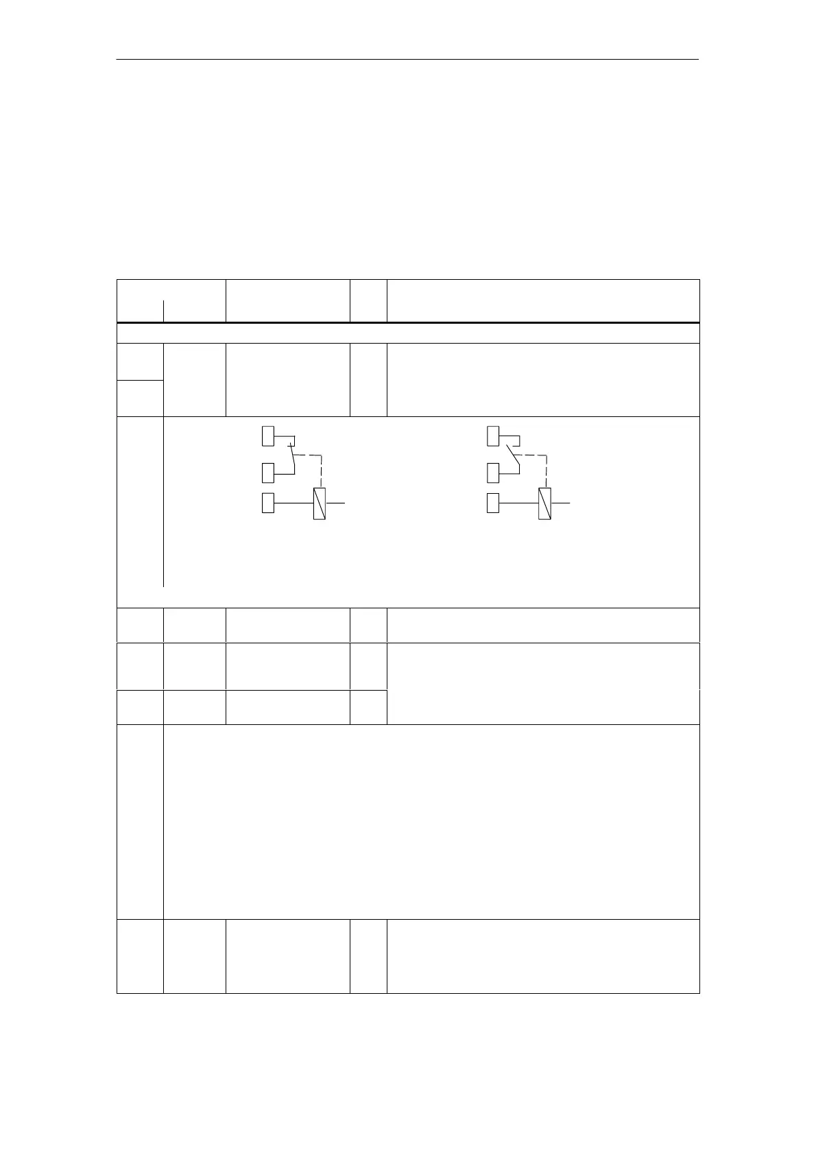
Relay, safe start inhibit
AS2
AS1
T.663
AS2
AS1
T.663
No pulse enable (terminal 663)
The gating pulses of the power
transistors are inhibited.
Pulse enable (terminal 663) available
The gating pulses of the power transistors are
enabled.
Relay, safe start inhibit
Terminals für supply and pulse enable (X431)
X431 Connector type: 5–pin plug connector
Max. conductor cross–section: 1.5 mm
2
P24 X431.1 External supply for digi-
tal outputs
(+24 V)
V
Voltage tolerance
(including ripple): 10 V to 30 V
M24 X431.2 Reference for external
supply
V
The external supply is required for the following digital outputs:
S 8 outputs of the drive–specific terminals (X461, O0.A – O3.A / X462, O0.B – O3.B )
S 8 outputs of the optional TERMINAL module (X432, O4 – O11)
When dimensioning the external supply, the total current of all of the digital outputs must be taken into
account.
Max. total current:
S for control modules (all 8 outputs): 2.4 A
S for the optional TERMINAL module (all 8 outputs): 480 mA
Example:
Board/module Outputs Dimensioning the external supply
Control board 8 max. 1.5 A ––> 24 V / 1.5 A
Control module +
Optional TERMINAL mod. 8 + 8 max. (1.5 A + 280 mA) ––> 24 V / 1.8 A
9 X431.3 Enable voltage
(+24 V)
V Reference: T.19
Max. current (for the complete group): 500 mA
Note:
The enable voltage (terminal 9) can be used to supply the
enable signals (e.g. pulse enable) as 24 V auxiliary voltage.
Module–
specific
terminals and
interfaces
5 Control Modules

 Loading...


