5
05.01
5.7 Control module ”SIMODRIVE 611 universal”
5-133
Siemens AG 2001 All rights reserved
SIMODRIVE 611 Planning Guide (PJU) – 05.01 Edition
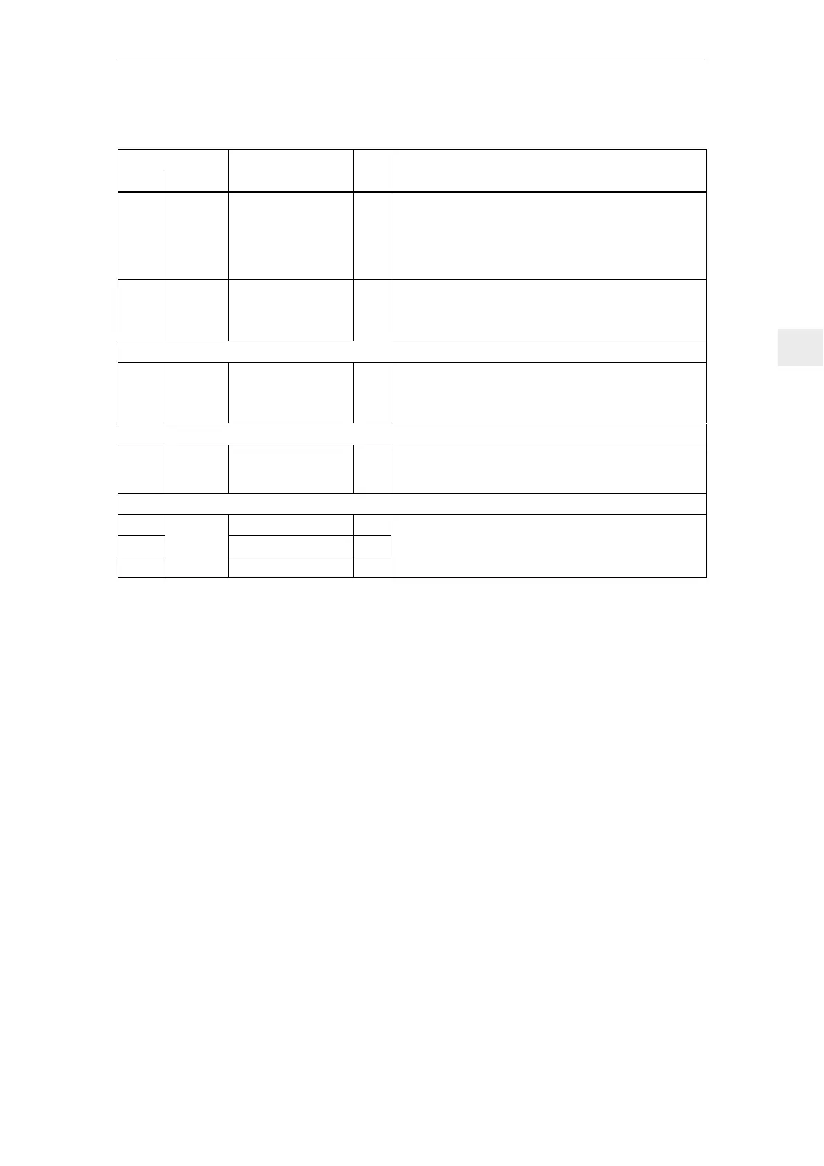
Table 5-17 Overview of the module–specific terminals and interfaces, continued
Terminal Technical dataType
1)
Function
No.
Technical dataType
1)
Function
Desig.
663 X431.4 Pulse enable
(+24 V)
I Voltage tolerance (including ripple): 21 V to 30 V
Current drain, typical: 25 mA at 24 V
Note:
The pulses are enabled for both drive A and B simultaneously.
The drives coast down, unbraked when the pulse enable is
withdrawn.
19 X431.5 Reference
(reference for all digital
inputs)
V Note:
If the enable signals are to be controlled from an external vol-
tage source, then the reference potential (ground) of the exter-
nal source must be connected to this terminal.
Serial interface (X471)
– X471 Serial interface for “Si-
moCom U”
IO Connector type: D–Sub socket, 9–pin
Cable plan and pin assignment for RS232 or RS485, refer to:
Reference:
/FB611U/, Description of Functions SIMODRIVE 611 universal
Equipment bus (X34)
– X351 Equipment bus IO Ribbon cable: 34–core
Voltages: Various
Signals: Various
Test socket (X34)
DAU1 Test socket 1
2)
M Test socket: ∅ 2 mm
DAU2
X34
Test socket 2
2)
M
Resolution: 8 bits
Voltage range: 0 V to 5 V
M Reference M
Voltage range: 0 V to 5 V
Max. current: 3 mA
1) I: Input; IO: Input/output; M: Measuring signal; NC: NC contact; V: supply
2) Can be freely parameterized
5 Control Modules

 Loading...


