9
05.01
9.2 Infeed modules
9-231
Siemens AG 2001 All rights reserved
SIMODRIVE 611 Planning Guide (PJU) – 05.01 Edition
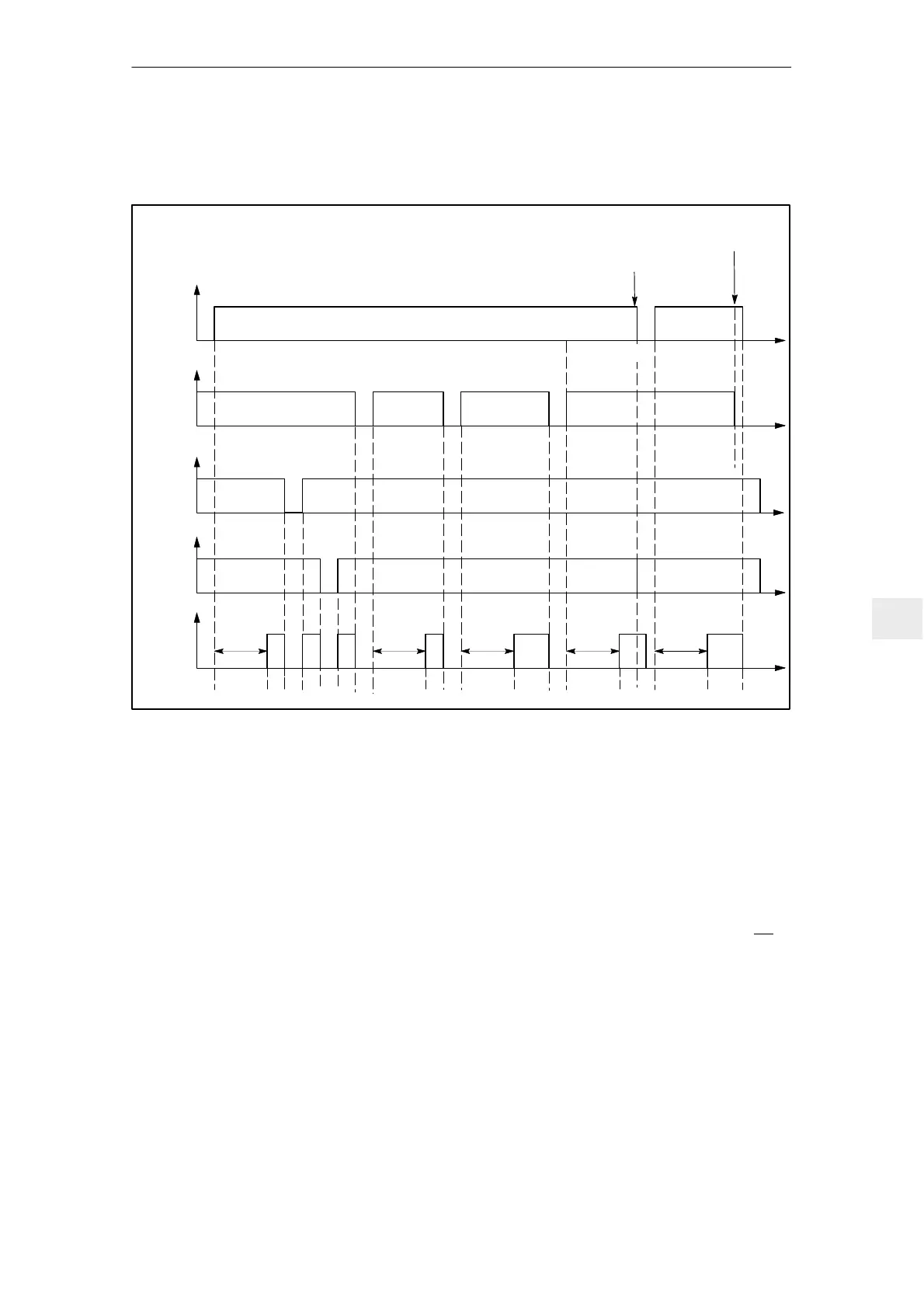
9.2.5 Timing diagram for the ready signal in the I/R module
Shutdown using the main switch, external line
contactor or another switching element.
Load
supply
available
C
Supply voltage
Supply failure
Supply voltage
B
T. 48
T. 64
T. 63
Ready
T. 72...74
A
AAA
A
Fig. 9-4 Timing diagram for the ready signal in the I/R module
Switch S1.2 = OFF, standard setting at the I/R module “Ready signal”
The ready relay can only pull in if the pre–charging sequence has been comple-
ted and the internal line contactor has pulled in.
The I/R module is internally inhibited during power failures, i.e. the I/R module
can no longer control (closed–loop) the DC link voltage which means that bra-
king energy can no longer be fed back into the line supply. The drives are not
inhibited, but the ready relay drops out with a delay, after the line failure detec-
tion time, dependent on the line impedances.
When the load supply is disconnected using the main switch or an external line
contactor, e.g. for a six–conductor connection (refer to Section 9.13) as well as
other switching elements, it must be ensured, that at least 10 ms beforehand,
terminal 48 at the I/R module is de–energized. This can be achieved, e.g. using
a main switch with leading contact or interlocking circuits for the external line
contactor or other switching elements.
A
B
C
9 Important Circuit Information

 Loading...


