3
05.01
3.6 High–resolution position (HGL)
3-77
Siemens AG 2001 All rights reserved
SIMODRIVE 611 Planning Guide (PJU) – 05.01 Edition
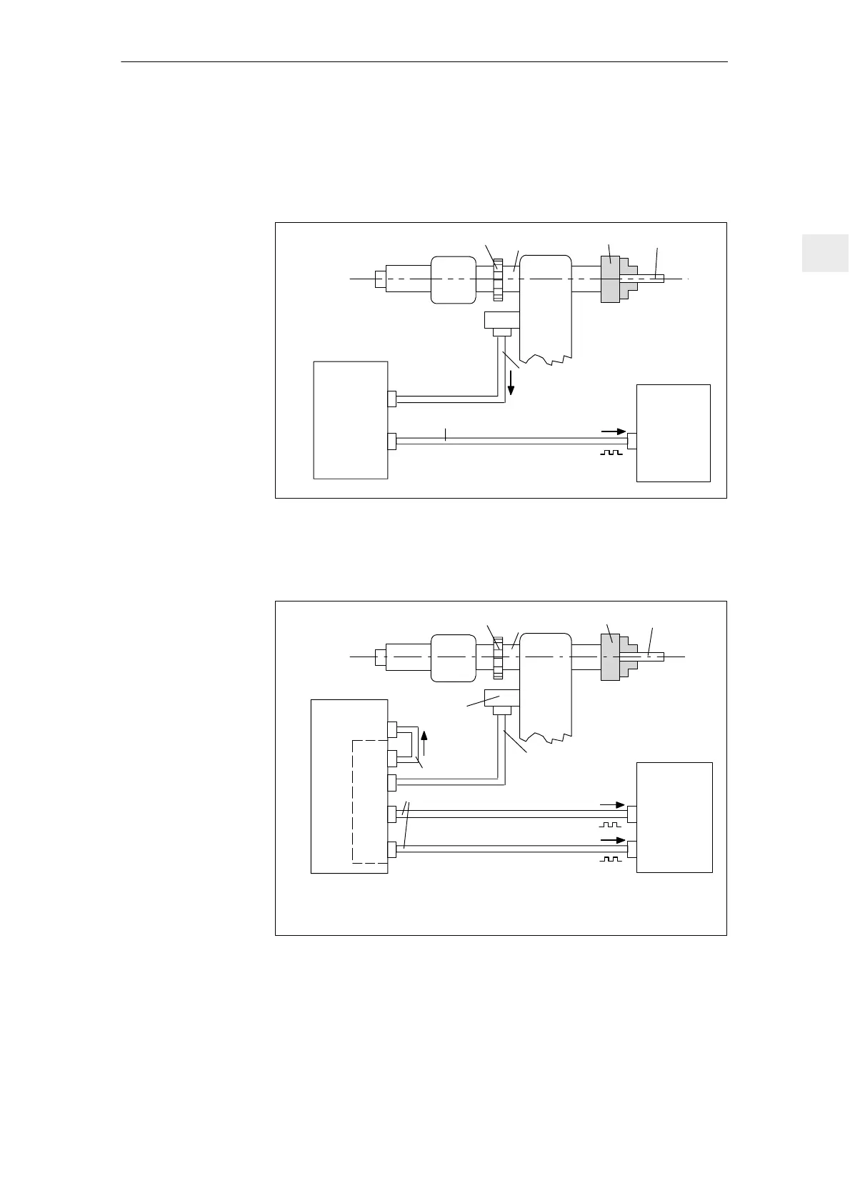
3.6.3 System configurations and cable connections
HGL is not required in this configuration.
6FX2002–2CA31–0VVV
Toothed/measuring wheel
Spindle
Chuck
Workpiece
Sensing
head
Drive
converter
611A
X412
X432
NC
Measuring
circuit 1,
standard
track
6FX2002–2CB11–0VVV
~
n
1
x pulse number/360
0
mech
n
1
= 1; 2; 4; 8
1PH2~
Fig. 3-11 System configuration, 1PH2 motor without C–axis operation
Drive
converter
611A
X412
HGL
X512
X511
X521
X522
6FX2002–2CA51–0VVV
6FX2002–2CB11–0VVV
~
n
2
x 175.78125 x pulse number/360
0
mech
n
2
= 1; 2
n
1
, n
2
= can be selected via switch S1
~
n
1
x pulse number/360
0
mech
n
1
= 1; 2; 4; 8
6FC9348–0FY
Toothed/measuring wheel
Spindle
Chuck
Workpiece
Sensing head
NC
Measuring
circuit 1,
standard
track
1PH2~
Measuring
circuit 2,
C–axis track
Fig. 3-12 System configuration, 1PH2 motor with C–axis operation
1PH2 motor
without C–axis
operation
1PH2 motors with
C–axis operation
3 Motor Selection, Position/Speed Sensing

 Loading...


