5
05.01
5.1 Feed control with user–friendly and analog setpoint interface 6SN1118–0AA11–0AA1
5-105
Siemens AG 2001 All rights reserved
SIMODRIVE 611 Planning Guide (PJU) – 05.01 Edition
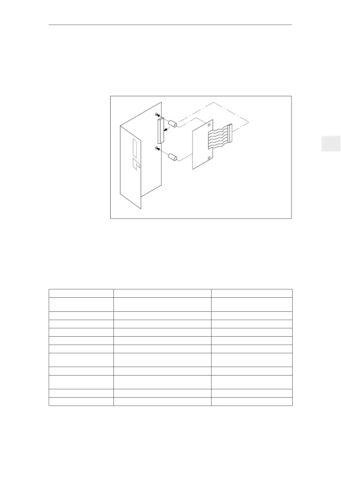
5.1.3 Option module, main spindle functions 6SN1114–0AA02–0AA0
Main spindle functions can also be realized using an option board (main spindle
drive option). In this case, the option board should be mounted on the control
board (this is only possible in conjunction with the user–friendly interface).
X305
Mount on studs using M3x6 screws.
Tightening torque, 0.8 Nm.
Insert the front connector into the front panel,
insert the PC board in the locating lugs.
Establish the connection using X305.
Fig. 5-2 Option board
Table 5-4 Function overview and settings on the MSD option
Parameter Value range Setting elements
Limit value stages
NC/NO
The relay outputs of the limit value stages can
be defined as NC or NO contacts
0 Ω resistors
|I
act
| > I
X
term. 110/108 4.5 %...100 % Pot. R211
| n
act
| < n
min
term. 115/114 0.3 %...1.7 % of n
max
Pot. R10
| n
act
| < n
X
term.216/214 3 %...100 % of n
max
Pot. R43
n
set
= n
set*
term. 127/126 n
set
difference< 20 mV Resistor R179
n < n
off
0.3 %...1.7 % of n
max
Pot. R1
Ramp–function generator via
terminals 56/14
10 ms...1.1 s
0.1 s...11 s (changeover 1:10)
Potentiometer R20
terminal 102
Tracking Active/inactive R270
Drift (main spindle drive ope-
ration)
–30 mV...+30 mV (referred to n
set
) Pot. R96
Proportional gain Reduce Kp to 0 %...95 % Pot. R45 + parameter board R25
Integral action time Extend T
N
to 100 %...1500 % Pot. R44 + parameter board R35
Installing the MSD
option
Function overview
and settings on the
MSD option
5 Control Modules

 Loading...


