10
05.01
10.1 Installation and connection regulations
10-308
Siemens AG 2001 All rights reserved
SIMODRIVE 611 Planning Guide (PJU) – 05.01 Edition
G
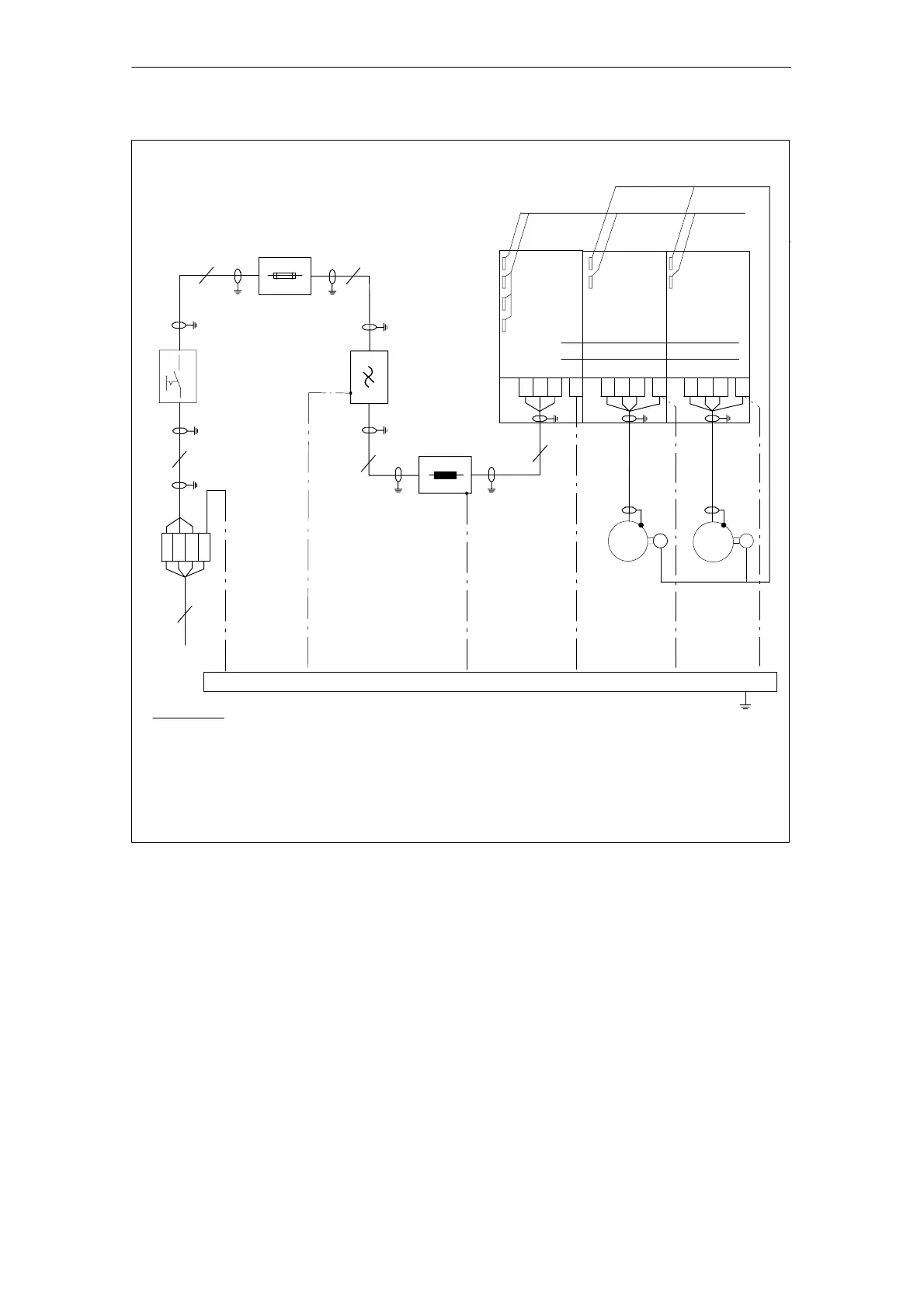
Function
cables
3) PE – rail is connected through a large surface area to the cabinet mounting panel
Cabinet mounting panel
1)
I/R module
or
U/I module
2)
MSD module Feed drive
module
P600
M600
2)
M
M
1)
1)
1)
1)
Supply
1) Shield connection, connected through the largest possible surface area with the cabinet mounting panel.
2) Shield connection at the module–specific connecting panel
Encoder cables
1)
1)
Fuses
Incoming terminals
Main switch
PE
PE
L2
L3
L1
PE
V1U1 1 W
3) The PE cables can be alternatively connected via PE rail, taking into consideration EN50178
(protective connections).
V2U2
2 W
PEV2U2
2 W
4
3
3
3
Reactor
1)
1)
3
3
LOAD LINE
PE
Filter
PE
2)
G
4) Refer to Sections 3.4.2 and 3.1 for permissible commutating reactors for I/R module sinusoidal operation
Refer to Section 3.4.2 for permissible commutating reactors for the 28 kW UI module
A clearance of > 100mm around the HF reactor must be provided at the cable entry into the cabinet.
4)
Fig. 10-1 Connection diagram for line filters for 5 kW and 10 kW UI modules, for I/R modules, 16 kW to 120 kW.
The connection diagram is also valid for UE 28 kW, however, as a result of the uncontrolled infeed, 6–pulse
squarewave current is present
10.1.1 Shield connecting plates
Shield connecting plates, which can be retrofitted, are available for the infeed
modules and power modules. Mounting points are available on these plates to
attach terminals to connect a brake.
10 Cabinet Design and EMC

 Loading...


