5
05.01
5.1 Feed control with user–friendly and analog setpoint interface 6SN1118–0AA11–0AA1
5-106
Siemens AG 2001 All rights reserved
SIMODRIVE 611 Planning Guide (PJU) – 05.01 Edition
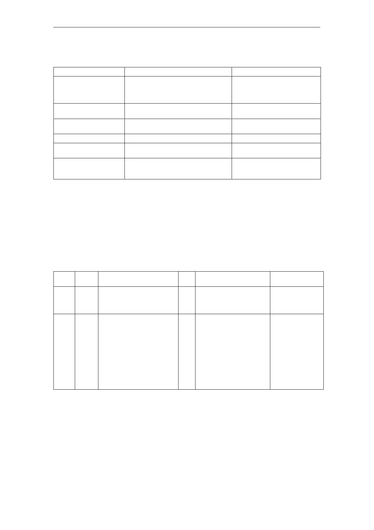
Table 5-4 Function overview and settings on the MSD option
Parameter Setting elementsValue range
Torque limiting Start of constant power 23 %...70 % n
max
Deviation –20 %...+20 % n
max
Constant limiting 10 %...100 % I
max
Speed–dependent limiting 1 %...85 % I
max
Pot. R214
Pot. R213
Resistor R76
Pot. R225
Changeover speed
MSD C–axis operation
0 %...100 % n
max
Resistor R77, R78
Select C axis operation, termi-
nal 61
10 V setpoint at term. 24/20 81/10 n
max
from
MSD operation
Speed actual value image Normalized n
rated
corresponds to +10 V Terminal 75
Current actual value image Normalized I
actN
= 10 V Terminal 162 if R160 = 1 k,
R207 = open
Power image Factor 1...3 Resistor R903
Terminal 162 if R160 = open,
R207 = 1 k
5.1.4 Interface overview, MSD option
Table 5-5 Interface overview, MSD option
Term.
No.
Desig. Function
Type
1
)
Typ. voltage/limit values Max. cross–sect.
102
61
75
162
X312
X312
X312
X312
TH = 1:10
C–axis operation
n
act
P
act
/I
act
2)
I
I
O
O
+13 V...30 V/R
E
=1.5 kΩ
+13 V...30 V/R
E
=1.5 kΩ
0 V...±10 V
0 V...±10 V
1.5 mm
2
1.5 mm
2
1.5 mm
2
1.5 mm
2
110
108
115
114
216
214
127
126
X322
X322
X322
X322
X322
X322
X322
X322
|I
act
| > I
X
n< n
min
n < n
X
n
set
= n
set*
NO/
NC
I
NO/
NC
I
NO/
NC
I
NO/
NC
I
30 V/1.0 A max.
30 V/1.0 A max.
30 V/1.0 A max.
30 V/1.0 A max.
30 V/1.0 A max.
30 V/1.0 A max.
30 V/1.0 A max.
30 V/1.0 A max.
1.5 mm
2
1.5 mm
2
1.5 mm
2
1.5 mm
2
1.5 mm
2
1.5 mm
2
1.5 mm
2
1.5 mm
2
1) I=input; O=output; NC=NC contact; NO=NO contact (for signal NO=high/NC=low)
2) Depending on the equipping version, power image (series) or current actual value image
Main spindle drive
option (only for
user–friendly
interface)
5 Control Modules

 Loading...


