5
05.01
5.5 Induction motor control with analog setpoint interface 6SN1122–0BA1_–0AA_
5-121
Siemens AG 2001 All rights reserved
SIMODRIVE 611 Planning Guide (PJU) – 05.01 Edition
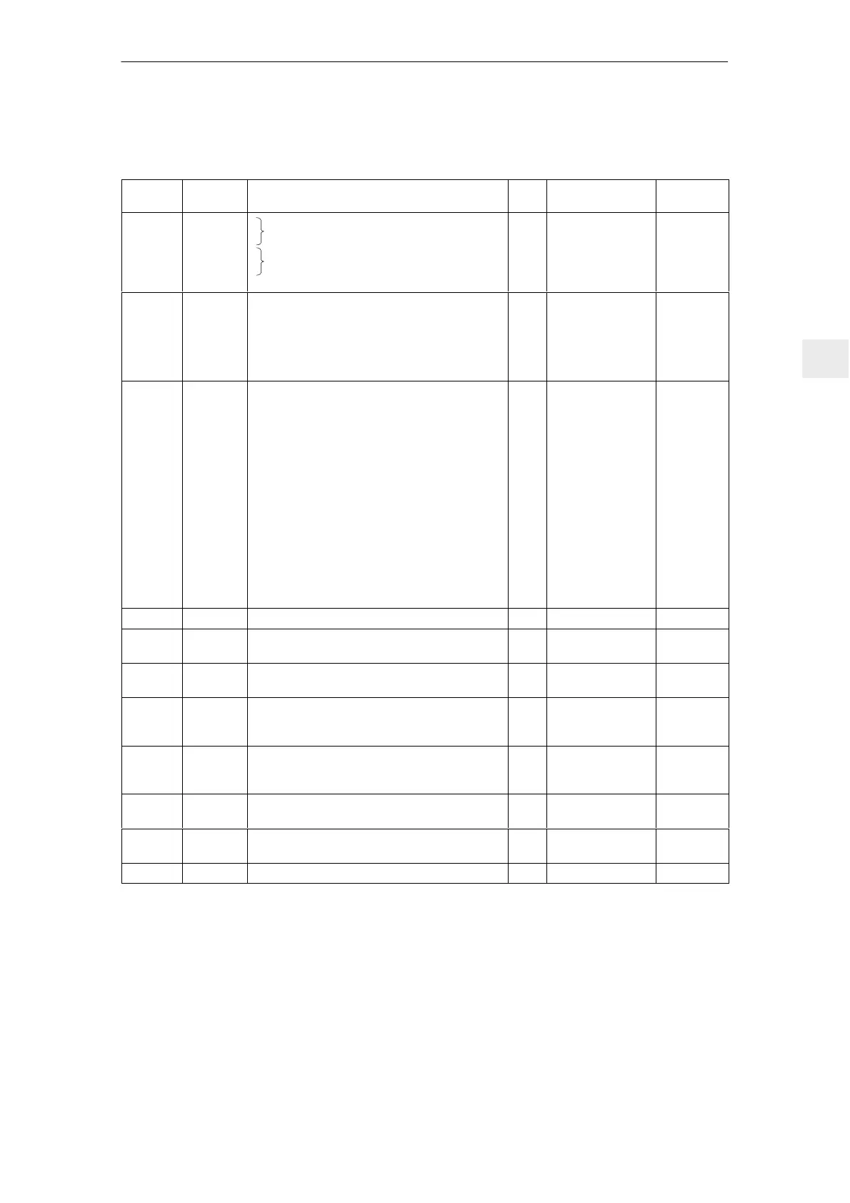
5.5.3 Interface overview, induction motor control
Table 5-15 Interface overview, induction motor control
Term.
No.
Desig. Function
Type
1)
Typ. voltage/limit
values
Max.
cross–sect.
56
14
24
8
X421
X421
X421
X421
Speed setpoint 1
Differential input
Speed setpoint 2
Differential input (supplementary setpoint)
2
I
I
I
I
0 V ... ±10 V
0 V ... ±10 V
1.5 mm
2
1.5 mm
2
1.5 mm
2
1.5 mm
2
A91
M
A92
M
X451
X451
X451
X451
Analog output DA1
Reference voltage for DA1
Analog output DA2
Reference voltage for DA2
Note: The analog output is only available with
the appropriate control version.
O
I
O
I
–10 V ... +10 V
max. 3 mA
–10 V ... +10 V
max. 3 mA
1.5 mm
2
1.5 mm
2
1.5 mm
2
1.5 mm
2
9
663
65
81
X431
X431
X431
X431
Enable potential 5)
Pulse enable: The relay ”start inhibit” is
energized using terminal 663, and when it
opens, the firing pulses are inhibited and the
motor is switched to a torque–free condition.
Controller enable: To power–up the drives, in
addition to terminal 65, terminals 663 and 81
must also be energized. If terminal 65 is opened,
the motor brakes with the selected deceleration
time (ramp–down time). The pulses are canceled
when n
min
is reached.
Ramp–function generator fast stop: The motor
brakes along the torque limit after terminal 81
has been opened. The pulses are canceled, or
the motor remains magnetized, when n
min
is
reached.
O
I
I
I
+24 V
+21 V ... 30 V
+13 V ... 30 V
+13 V ... 30 V
1.5 mm
2
1.5 mm
2
1.5 mm
2
1.5 mm
2
E1 to E9 X431 Freely–programmable select terminals I +13 V ... 30 V 1.5 mm
2
X432 Connecting a BERO to monitor the maximum
speed
3)4)
D–Sub
15–pin
AS1
AS2
X441
X441
Relay, start inhibit (checkback signal, term. 663)
Relay, start inhibit (checkback signal, term. 663)
NC
max. 250V
AC
/1A
30 V
DC
/2 A
1.5 mm
2
1.5 mm
2
A11 to
A61
289
X441
X441
Freely–programmable relay signals
Relay contact supply
NO
I
30 V/1 A
30 V/6 A
1.5 mm
2
1.5 mm
2
672
673
674
X441
X441
X441
Axis–specific signal
Ready or
fault
NO
I
NC
30 V/1 A
30 V/1 A
30 V/1 A
1.5 mm
2
1.5 mm
2
1.5 mm
2
RS 232C X411 Serial interface for computer–supported
start–up (start–up program)
D–Sub
9–pin
X412 Possibility of connecting a motor temperature sen-
sor KTY84 acc. to IEC 134
3)
or PTC
D–Sub
15–pin
X151/351 Equipment bus
1) I=input; O=output; NC=NC contact; NO=NO contact (for signal, NO=high, closed / NC=low, open)
2) Only available for the appropriate control version; the shields of the setpoint cable should be connected at both ends
3) X412, X432 is only available for Order No. 6SN1122–0BA11–0AA1.
4) BERO type: 3–conductor PNP NO contact, e.g. BERO M30 Order No.: 3RG4014–0AG01 or
BERO M12 Order No.: 3RG4012–3AG01
The BERO cable/motor temperature sensing cable must be shielded.
5) The terminal may only be used to enable the associated drive group
5 Control Modules

 Loading...


