7
05.01
7.2 Line filter and HF commutating reactors for I/R and UI modules
7-215
Siemens AG 2001 All rights reserved
SIMODRIVE 611 Planning Guide (PJU) – 05.01 Edition
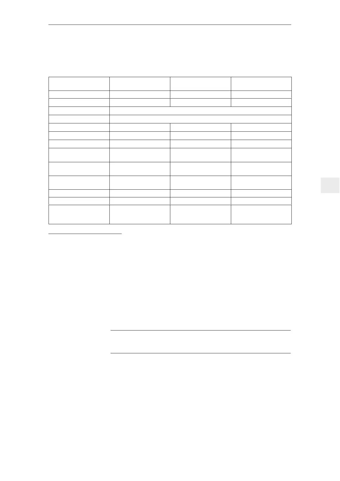
7.2.2 Assignment of the line filters to the UI modules
Table 7-11 Assignment of the line filter to the UI modules
UI module
5/10 kW
UI module
10/25 kW
UI module
28/50 kW
Filter components Line filter, 5 kW Line filter, 10 kW Line filter, 28 kW
Order No., 6SN1111–0AA01–1BA0 6SN1111–0AA01–1AA0 6SN1111–0AA01–1CA0
Mounting position Any
Module width Refer to Dimension Drawings, Section 12
Filter Filter 3.8 kg 5.7 kg 12.5 kg
I
rated
filter 16 A 25 A 65 A
P
v
filter 20 W 20 W 25 W
Connection 4 mm
2
PE, M6 studs
10 mm
2
PE, M6 studs
50 mm
2
PE, M10 studs
Terminals,
Line supply input
LINE
L1, L2, L3, PE
LINE
L1, L2, L3, PE
LINE
L1, L2, L3, PE
Terminals,
output
LOAD
L1, L2, L3, PE
LOAD
L1, L2, L3, PE
LOAD
L1, L2, L3, PE
I
rated
fuse
1)
16 A 25 A 80 A
Cooling Non–ventilated Non–ventilated Non–ventilated
Radio interference suppres-
sion
EN 55011
Cable–borne,
limit value Class A
Cable–borne,
limit value Class A
Cable–borne,
limit value Class A
1) The fuse used must have this rated current. Refer to Table 7-1 for recommended fuses.
7.2.3 Adapter set and line filter package
Line filter packages are available for the I/R modules (refer to Catalog NC60).
These line filter packages comprise a line filter and an HF commutating reactor
(refer to Table 7-10).
We recommend that these line filter packages are ordered.
Adapter sets are available to adapt the line filter packages to the mounting sur-
face and to the retaining points of the earlier filter modules. The mounting depth
protrudes beyond the front of the drive group by 20 – 30 mm.
Note
It is not permissible that the filter inputs and outputs are interchanged.
J
7 Line Supply Connection

 Loading...


