6
05.01
6.4 Interface overview
6-180
Siemens AG 2001 All rights reserved
SIMODRIVE 611 Planning Guide (PJU) – 05.01 Edition
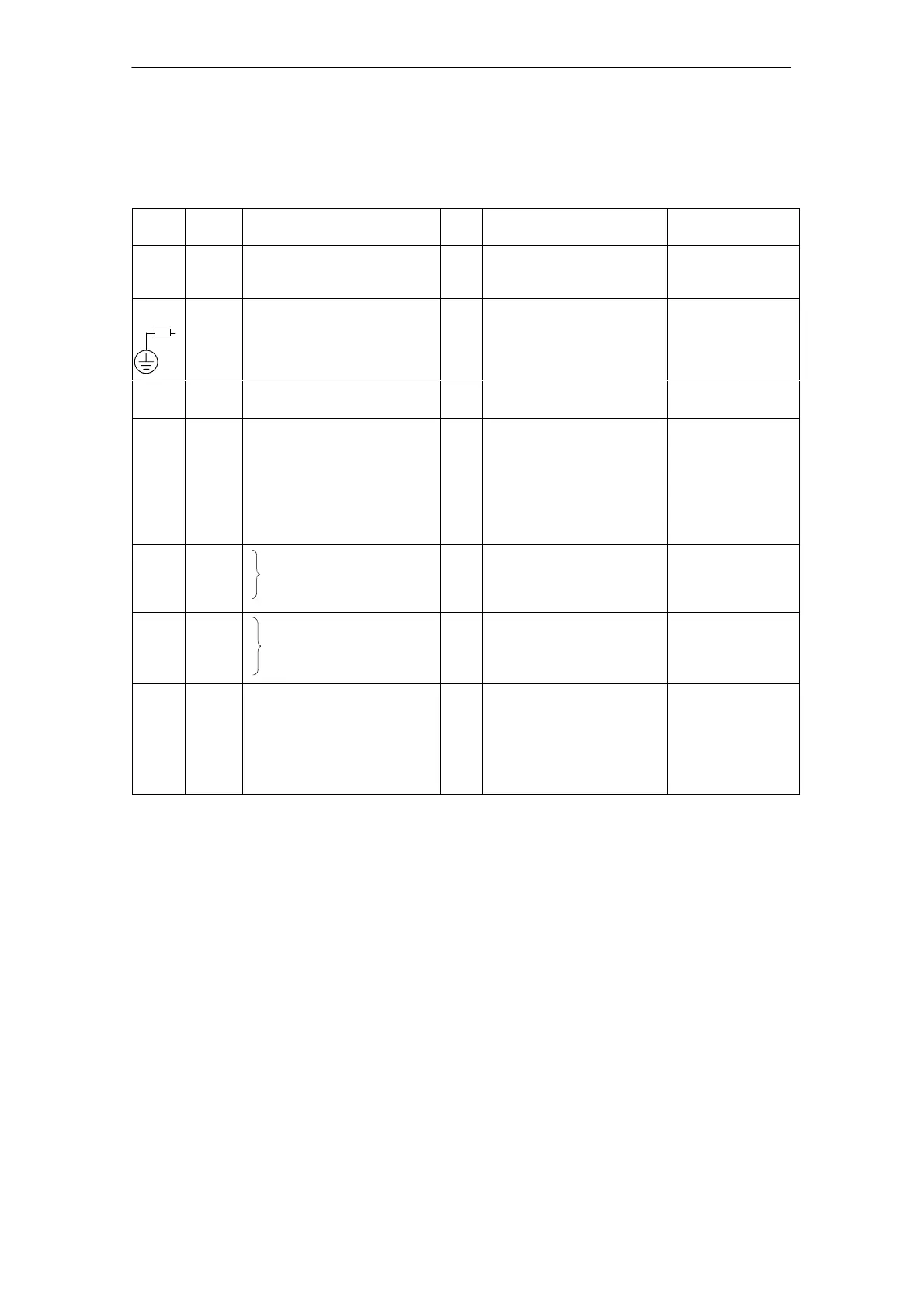
6.4.2 Interface overview, 5 kW UI module
Table 6-7 Interface overview, 5 kW UI module
Term.
No.
Desig. Function
Type
1)
Typ. voltage/limit values
Max. cross–section
6)
U1
V1
W1
X1 Supply connection I 3–ph. 400 V AC 4 mm
2
finely stranded
without end sleeves
6 mm
2
with cable lug
PE –
X131
X351
Protective conductor
Electronics M
Equipment bus
Grounding bar
3)
I
I
I/O
I/O
0 V
0 V
Various
–300 V
M5 thread
M4 thread
34–core ribbon cable
Busbar
P600
M600
DC link I/O +300 V
–300 V
Busbar
M500
P500
1U1
2U1
1V1
2V1
1W1
2W1
X181
X181
X181
X181
X181
X181
X181
X181
DC link power supply
DC link power supply
Output L1
Input L1
Output L2
Input L2
Output L3
Input L3
I
I
O
I
O
I
O
I
–300 V
+300 V
3–ph. 400 V AC
3–ph. 400 V AC
3–ph. 400 V AC
3–ph. 400 V AC
3–ph. 400 V AC
3–ph. 400 V AC
1.5 mm
2
1.5 mm
2
1.5 mm
2
1.5 mm
2
1.5 mm
2
1.5 mm
2
1.5 mm
2
1.5 mm
2
5.3
5.2
5.1
nc
X121A
X121A
X121A
X121A
Relay contact
group signal
I
2
t/motor temp.
NC
NO
I
50 V DC/0.5 A/12 VA max
5 V DC/3 mA min
1.5 mm
2
1.5 mm
2
1.5 mm
2
1.5 mm
2
74
73.2
73.1
72
X121B
X121B
X121B
X121B
Relay signal
Ready/fault
NC
I
I
NO
1AC 250 V/DC 50 V/2 A max
1DC 5 V/3 mA min
1.5 mm
2
1.5 mm
2
1.5 mm
2
1.5 mm
2
63
2)
9
2)4)
9
2)4)
64
2)
R
5)
19
X141AX
141A
X141A
X141A
X141A
X141A
Pulse enable
FR+
FR+
Drive enable
RESET
FR, reference ground enable
voltage
I
O
O
I
I
O
+13 V...30 V/R
E
= 1.5 kΩ
+24 V
+24 V
+13 V...30 V/R
E
= 1.5 kΩ
term.19/R
E
= 10 kΩ
1.5 mm
2
1.5 mm
2
1.5 mm
2
1.5 mm
2
1.5 mm
2
1.5 mm
2
1) I = input; O = output; NC = NC contact; NO = NO contact
2) Terminal 19 is the reference terminal (connected in the module to 10 k to general reference ground X131)
Terminal 15 may neither be connected to PE nor to terminal 19, furthermore, it is not permissible that external
voltage sources are connected to terminal 15. Terminal 19 may be connected to terminal X131.
The terminal may only be used to enable the associated drive group.
3) The grounding bar is used to ground the DC link M rail through 100 kΩ (this should be preferably inserted;
if the system is subject to a high–voltage test, the grounding bar should be opened).
4) Max. current load of terminal 9 - terminal 19 1 A
Notice: UI 5 kW does not have terminals 7, 45, 44 and 10.
5) RESET = Reset the fault memory, edge triggered for the complete drive group
(term. ”R” term. 19 = RESET)
6) For UL certification, only use copper cables designed for an operating temperature of w 60
6 Infeed Modules

 Loading...


