6
05.01
6.4 Interface overview
6-181
Siemens AG 2001 All rights reserved
SIMODRIVE 611 Planning Guide (PJU) – 05.01 Edition
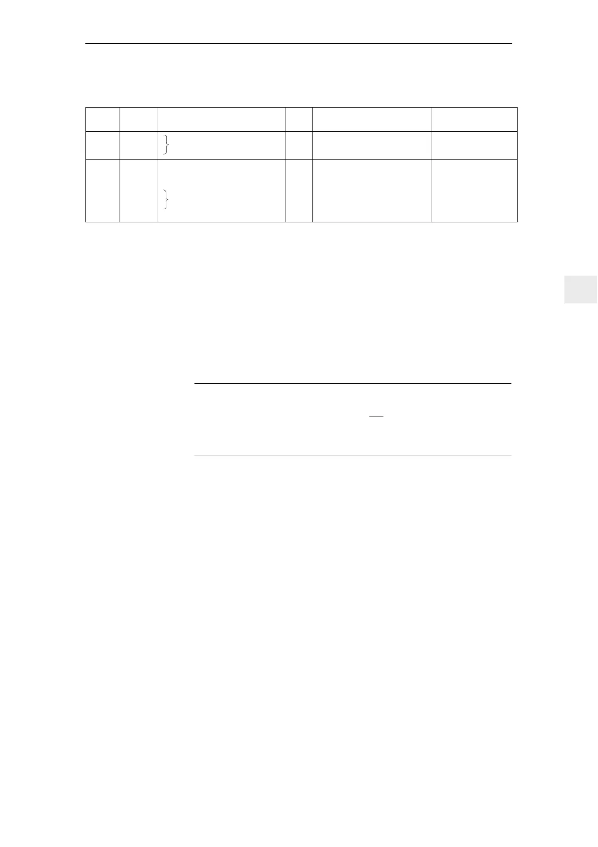
Table 6-7 Interface overview, 5 kW UI module
Term.
No.
Max. cross–section
6)
Typ. voltage/limit values
Type
1)
FunctionDesig.
111
213
X161
X161
Signaling contact
Line contactor
I
NC
1–ph. 250 V AC/50 V DC/2 A
17 V DC/3 mA min
1.5 mm
2
1.5 mm
2
9
2)4)
112
48
NS1
NS2
15
X141B
X141B
X141B
X141B
X141B
X141B
FR+
Setting–up/normal operation
contactor control
M
Coil contact for line,
pre–charging contactor
O
I
I
O
I
O
+24 V
+13 V...30 V/R
E
= 1.5 kΩ
+13 V...30 V/R
E
= 1.5 kΩ
+24 V
0/+24 V
0 V
1.5 mm
2
1.5 mm
2
1.5 mm
2
1.5 mm
2
1.5 mm
2
1.5 mm
2
1) I = input; O = output; NC = NC contact; NO = NO contact
2) Terminal 19 is the reference terminal (connected in the module to 10 k to general reference ground X131)
Terminal 15 may neither be connected to PE nor to terminal 19, furthermore, it is not permissible that external
voltage sources are connected to terminal 15. Terminal 19 may be connected to terminal X131.
The terminal may only be used to enable the associated drive group.
3) The grounding bar is used to ground the DC link M rail through 100 kΩ (this should be preferably inserted;
if the system is subject to a high–voltage test, the grounding bar should be opened).
4) Max. current load of terminal 9 - terminal 19 1 A
Notice: UI 5 kW does not have terminals 7, 45, 44 and 10.
5) RESET = Reset the fault memory, edge triggered for the complete drive group
(term. ”R” term. 19 = RESET)
6) For UL certification, only use copper cables designed for an operating temperature of w 60
Notice: UI kW does not have terminals 7, 45, 44 and 10.
Note
For UI 5 kW, the DC link is pre–charged via two phases.
If a DC link voltage is not established (there is no ready signal) even if all of the
enable signals are present, then a check must be made as to whether all of the
three phases are present at terminals U1, V1, W1.
6 Infeed Modules

 Loading...


