6
05.01
6.4 Interface overview
6-179
Siemens AG 2001 All rights reserved
SIMODRIVE 611 Planning Guide (PJU) – 05.01 Edition
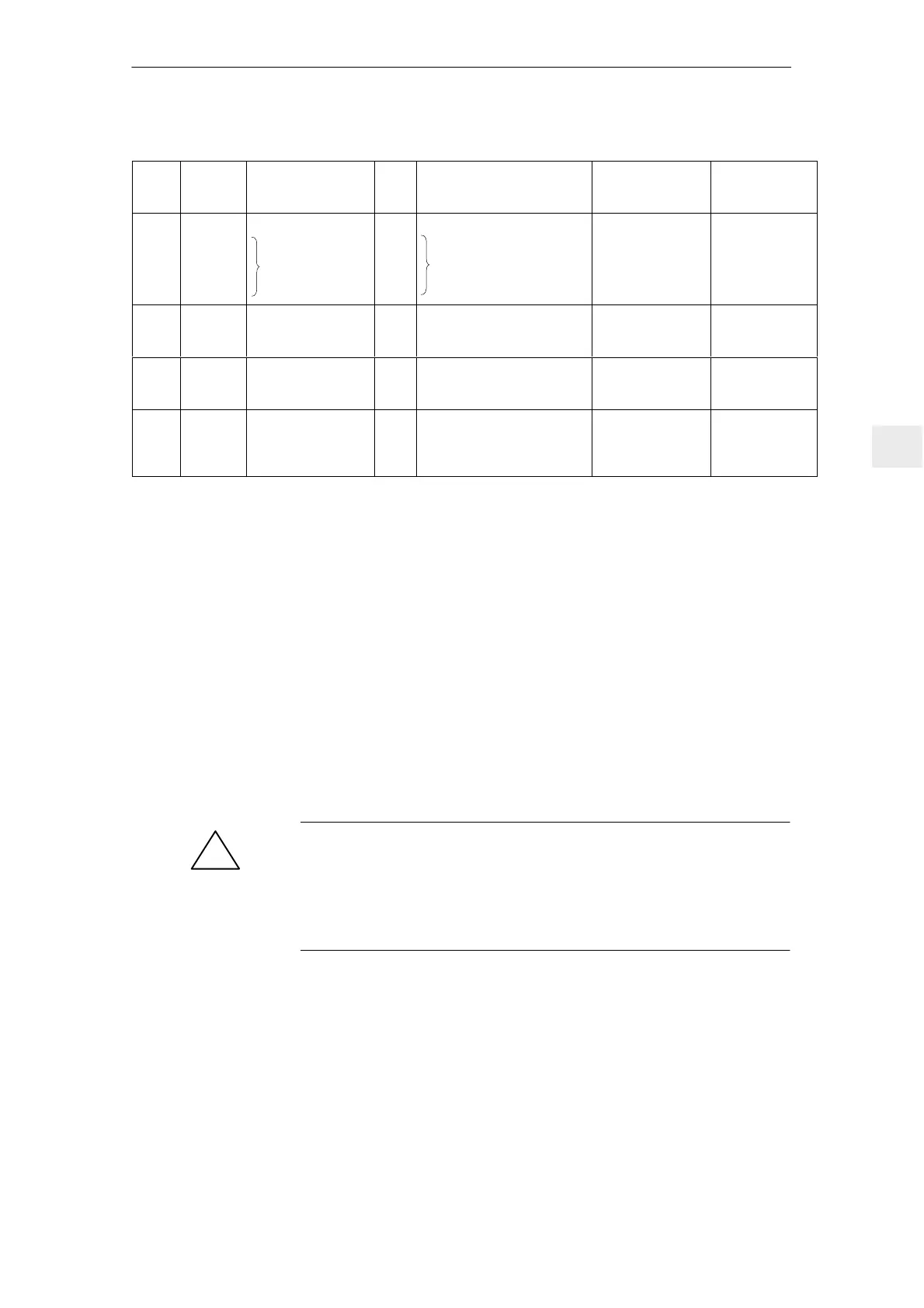
Table 6-6 Interface description for NE modules
Term.
No.
Terminals
available in
3)
Max. cross–
section
10)
Typ. voltage/ limit values
Type
1)
FunctionDesig.
48
2)
111
7)
213
7)
113
7)
X161
X161
X161
X161
Contactor control
Signaling contacts
Line contactor
I
I
NC
NO
+13 V...30 V/R
E
= 1.5 kΩ
+30 V/1 A (111–113)
1–ph. 250 V AC/50 V DC/
2 A max
17 V DC/3 mA min
1.5 mm
2
1.5 mm
2
1.5 mm
2
1.5 mm
2
I/R, UI
AS1
AS2
X172
X172
Signaling contact
Start inhibit (terminal
112)
I
NC
250 V AC / 1 A / 50 V DC/ 2A
max
5 V DC/10 mA min
1.5 mm
2
1.5 mm
2
I/R
NS1
NS2
X171
X171
Coil contact for line,
pre–charging contac-
tor
O
I
+24 V 1.5 mm
2
1.5 mm
2
I/R, UI
19
50
X221
X221
Enable voltage,
reference potential
Control contact for
fast discharge
O
I
0 V
0 V
1.5 mm
2
1.5 mm
2
Pulsed resistor
1) I = input; O = output; NC = NC contact; NO = NO contact; (for signal, NO = high; NC = low)
2) Terminal 19 is the reference ground (connected in the module with 10 k to a general reference ground,
X131/terminal 15)
Terminal 15 may neither be connected to PE nor to terminal 19, furthermore, it is not permissible
that external voltage sources are connected to terminal 15. Terminal 19 may be connected to terminal X131.
The terminal may only be used to enable the associated drive group.
3) I/R = Infeed/regenerative feedback module; UI = Uncontrolled infeed; MM = Monitoring module;
PW = Pulse resistor module
4) The 1st number is valid for cable lugs. The 2nd number is valid for finely–stranded conductors without conn. sleeves.
5) The grounding bar is used to ground the DC link M rail through 100 kΩ (this should be preferably inserted;
if the system is subject to a high voltage test, the grounding bar should be opened).
6) RESET = reset the fault memory, edge–triggered for the complete drive group (terminal ”R” terminal 15 = RESET)
7) Terminal 111–213 positively–driven NC contact (for I/R 16 kW and UI 10 kW, only from Order No. [MLFB]:
6SN114V–1VV01–0VVV)
Terminals 111–113 NO contact, not positively driven
8) Maximum current load of terminal 9 with respect to 19: 0.5 A.
9) Only for UI 28 kW
10) For UL certification, only use copper cables designed for an operating temperature of w 60
v
v
!
Warning
In order to prevent damage to the infeed circuit of the NE modules, when
energizing terminal 50 at X221 (DC link fast discharge), ensure that terminal 48
of the NE module is de–energized (electrically isolated from the line supply).
The checkback signal contacts of the main contactor of the NE module must be
evaluated (X161 terminal 111, terminal 113, terminal 213).
6 Infeed Modules

 Loading...


