5
05.01
5.7 Control module ”SIMODRIVE 611 universal”
5-134
Siemens AG 2001 All rights reserved
SIMODRIVE 611 Planning Guide (PJU) – 05.01 Edition
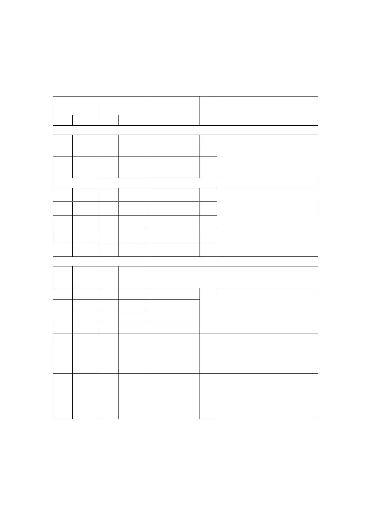
The drive–specific terminals are available for drive A and for drive B.
Table 5-18 Overview of the drive–specific terminals
Terminal
Function Type Technical data
Drive A Drive B
1)
No. Desig. No. Desig.
Encoder connection (X411, X412)
– X411 – – Motor encoder con-
nection
Drive A
I Refer to Section 3
Note:
Encoder limiting frequencies:
– – – X412 Motor encoder con-
nection
Drive B
I
S Encoders with sin/cos 1 V
pp
: 350 kHz
S Resolver: 375 Hz
Analog outputs (X441)
75.A X441.1 – – Analog output 1
2)
AO Connector type: 5–pin plug connector
Connection:
16.A X441.2 – – Analog output 2
2)
AO
Connection:
Cable with braided shield, connect at both
ends
– – 75.B X441.3 Analog output 1
2)
AO
Max. conductor cross–section for finely–
stranded or solid conductors: 0.5 mm
2
– – 16.B X441.4 Analog output 2
2)
AO
Voltage range: –10 V to +10 V
Max. current: 3 mA
Resolution: 8 bits
15 X441.5 15 X441.5 Reference –
Resolution: 8 bits
Updated: in the speed controller clock cycle
Short–circuit proof
Drive–specific terminals (X451, X452)
X451 X452 Connector type: 10–pin, plug connector strip
Max. conductor cross–section for finely–stranded or solid conductors:
0.5 mm
2
56.A X451.1 56.B X452.1 Analog input 1 AI Differential input
14.A X451.2 14.B X452.2 Reference
Voltage range: –12.5 V to +12.5 V
Input resistance: 100 kΩ
24.A X451.3 24.B X452.3 Analog input 2
Resolution: 14 bits (sign + bits)
Connection:
20.A X451.4 20.B X452.4 Reference
Connect a cable with braided shield at both
ends
65.A X451.5 65.B X452.5 Controller enable
Drive–specific
I Current drain, typical: 6 mA at 24 V
Signal level (including ripple)
High signal level: 15 V to 30 V
Low signal level: –3 V to 5 V
Electrical isolation: Reference is terminal
19 / terminal M24
9 X451.6 9 X452.6 Enable voltage
(+24 V)
V Reference: T.19
Maximum current
(for the total group): 500 mA
Note:
The enable voltage (terminal 9) can be used
to supply the enable signals (e.g. controller
enable).
Drive–
specific
terminals
5 Control Modules

 Loading...


