6
05.01
6-163
Siemens AG 2001 All rights reserved
SIMODRIVE 611 Planning Guide (PJU) – 05.01 Edition
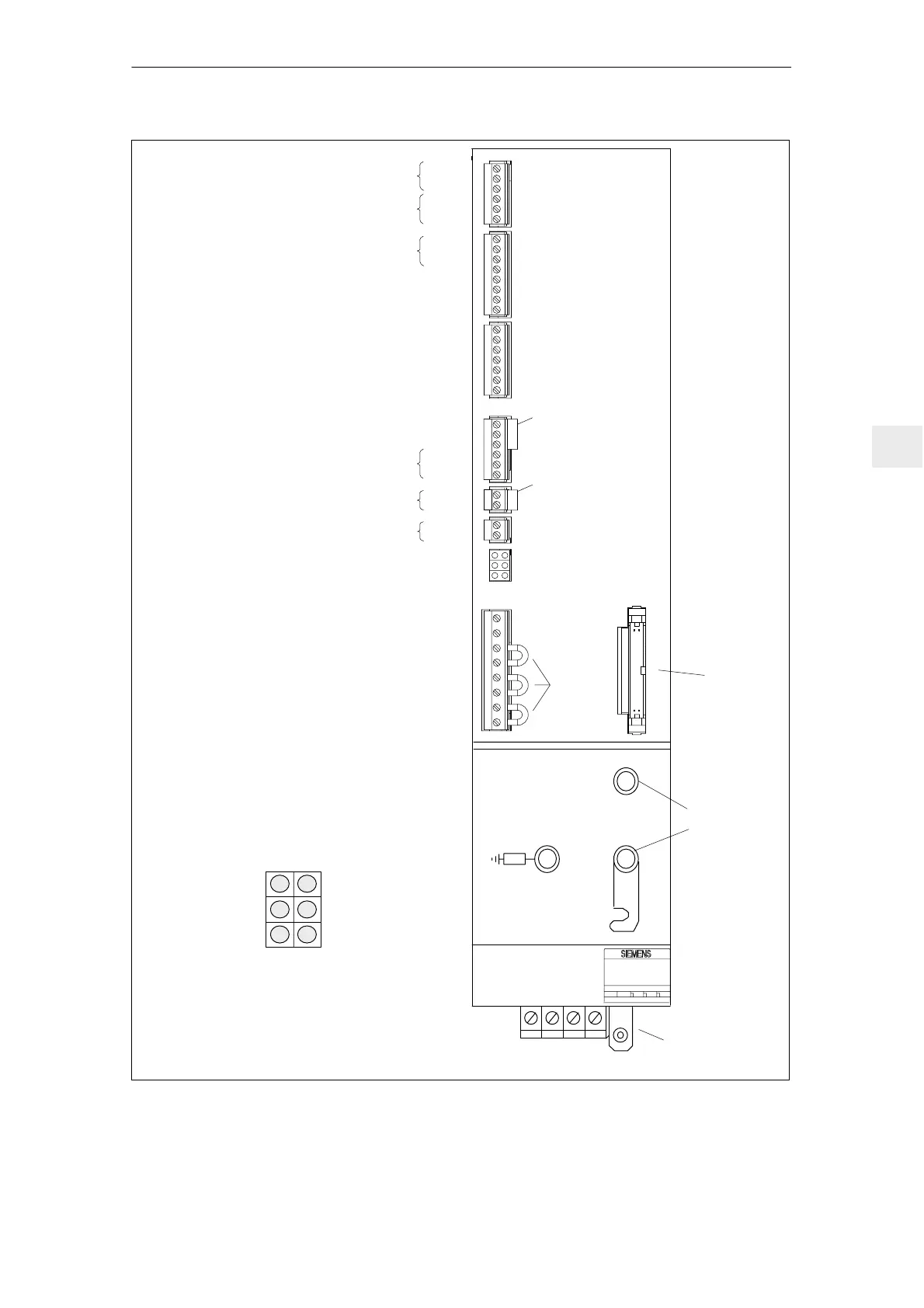
M600
P600
X351
X111
X121
X141
X161
X171
X172
X181
U1 V1 W1 X131 PE
Red
Yellow
Red
5V voltage
faulted
Equipment ready
(DC link
pre–charged)
Overvoltage
DC link
Electronics power
supply faulted
Equipment not
ready, enable
signal missing
(term. 63,
64 or 48)
Line supply fault
Supply connection
Equipment
bus
DC link
connection
Red
Green
Red
LED
displays
5.3
5.2
5.1
63
9
9
64
19
74
73.1
73.2
72
7
45
44
10
15
15
R
9
112
48
111
113
NS 2
NS 1
AS2
AS1
Relay contact,
ready signal
NC contact
NC contact
Relay contact, group signal I
2
t and
motor overtemperature
Pulse enable
Enable voltage
Drive enable
Enable voltage, reference potential
Enable voltage
P24
P15
N15
N24
M
M
RESET (R+Kl15)
Enable voltage
Setting–up operation
Contactor control, Start
213
Signal contact from
the line contactor
Enable signal for internal line contactor
Signal contact, start inhibit (NC contact)
M500
P500
2U1
1U1
2V1
1V1
2W1
1W1
DC link power supply for power failure buffering
External supply for the electronics power supply
External supply for the electronics power supply
External supply for the electronics power supply
1)
1)
1) jumpers inserted when the equipment is shipped
LED displays
1)
Fig. 6-2 Infeed/regenerative feedback module
6 Infeed Modules

 Loading...


