5
05.01
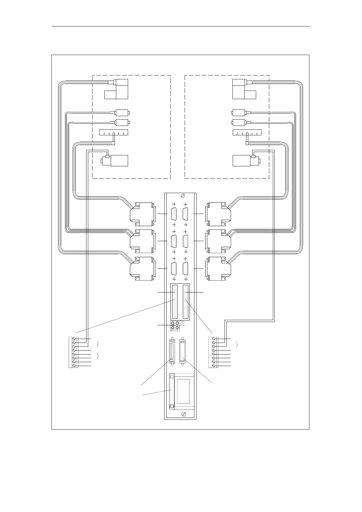
5.9 Control module ”HLA module”
5-146
Siemens AG 2001 All rights reserved
SIMODRIVE 611 Planning Guide (PJU) – 05.01 Edition
C2
B1
Axis 1
BERO input, axis 1
X1141
X1341
Position
HLA
Equipment bus interface (X151)
–X111
–X112
–X121
–X122
Hydraulic drive, axis 1
Pressure sensing
Control valve
–X101
–X102
Shut–off value, axis 1
26.5 V external supply
Enable voltage +24 V internal
Drive bus/terminating connector, drive bus
at the last module
–X34
–X35
Shut–off valve, axis 2
BERO input, axis 2
Power enable terminal 663
Enable voltage, 0 V internal
Enable voltage, +24 V internal
Control valve
Pressure sensor A
Hydraulic drive, axis 2
Position sensing
Pressure sensor B
Shut–off valve
Electronics ground
Reserved, do not assign
Electronics ground
Reserved, do not assign
Position
Pressure sensing
Control valve
Control valve
Pressure sensor A
Position sensing
Pressure sensor B
Shut–off valve
Axis 2
Drive bus
+
–
+
–
+
–
X431 X432
A
B
A
B
A
B
A
B
A
B
PV1
C1
M24
P24
M
MV1
663
9
PV2
19
M
MV2
B2
9
DAUs
measuring
system
system
measuring
Fig. 5-14 Connection configuration, HLA module
5 Control Modules

 Loading...


