6
05.01
6.5 Monitoring module
6-185
Siemens AG 2001 All rights reserved
SIMODRIVE 611 Planning Guide (PJU) – 05.01 Edition
DIL switch
Ready/
fault
signal
I
2
t – pre–alarm
and motor
overtemperature
Drive
enable
Pulse
enable
Reset
Terminal 112
setting–up
operation
3)
Equipment
bus
X151
Moni–
toring
NS 1 X131
Electronics power supply
112 19
FR–
9R15151044457
MN24N15P15P24
639964
FR+
Power supply and
signals
Equipment ena-
ble
V
act
5.372 73.1 73.2 74 5.25.1
DC link
sensing
6
2)
1
1)
S1 2
1)
3
1)
4
1)
5
1)
P600
M600
Line supply
rectification and
synchronization
M500P500
2W1
X131
PE
PE1 M600P600
Setting, refer to
Section 6
L1 L2 L3
START
AB
Switches
S1.3/1.5/1.6 have no
function
1W1 2W1 1V1 2V1 1U1
AB
1) Condition when supplied, OFF
2) Condition when supplied, ON
3) Jumpers closed when supplied
Term. 1U1–2U1, 1V1–2V1, 1W1–2W1
Term. 9–112
3)
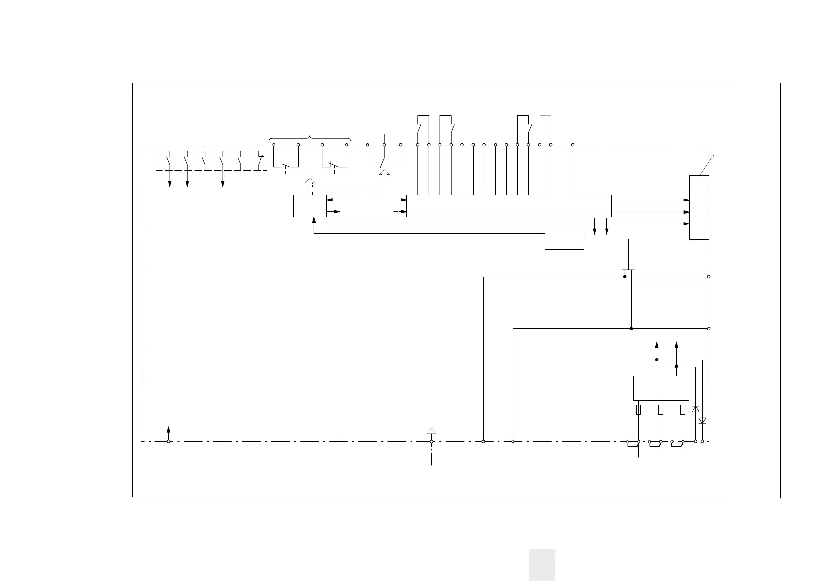
Fig. 6-10 Block diagram, monitoring module
6 Infeed Modules

 Loading...


