6
05.01
6.6 DC link options
6-193
Siemens AG 2001 All rights reserved
SIMODRIVE 611 Planning Guide (PJU) – 05.01 Edition
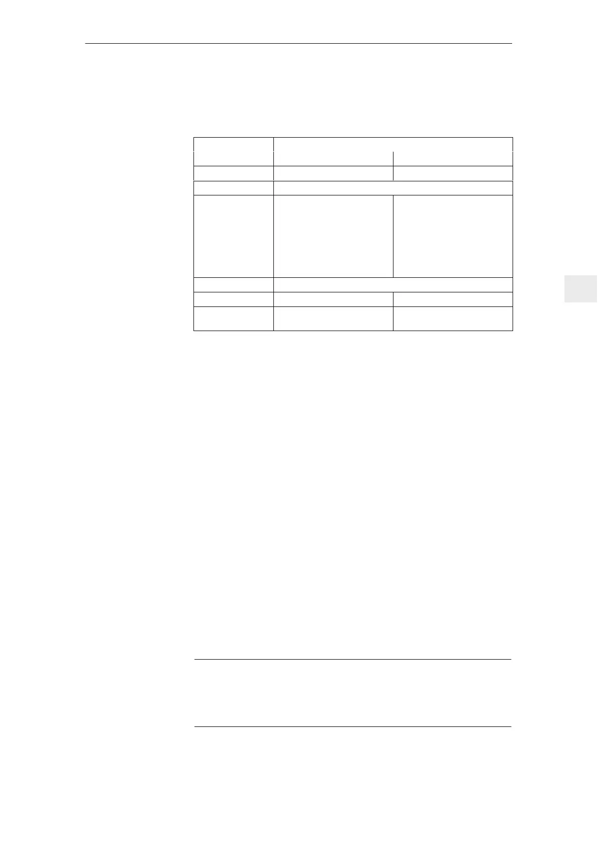
The following technical data apply:
Table 6-13 Technical data of the capacitor modules
Desig. Module
4.1 mF 20 mF
Order number 6SN1 112–1AB00–0BA0 6SN1 112–1AB00–0CA0
Voltage range V 350 to 750 V DC
Storage capacity
w = 1/2 x C x U
2
V
DC
steady–state
(examples)
600 V ––> 738 Ws
680 V ––> 948 Ws
V
DC
steady–state
(examples)
600 V ––> 3 215 Ws
680 V ––> 4 129 Ws
Note:
The voltage at the capacitors is
only approx. 0.94 x V
DC
as a
result of the internal pre–char-
ging resistor.
Temperature range 0 _C to +55 _C
Weight approx. 7.5 kg approx. 21.5 kg
Dimensions W x H x D
100 x 480 x 211 [mm]
W x H x D
300 x 480 x 211 [mm]
The energy storage capacity in dynamic operation and for regenerative
braking is calculated as follows:
Formula: w = ½ x C x (V
2
DC
link
max
– V
2
DC
link
n
)
Assumptions for the example:
Capacitance of the capacitor battery C = 4.1 mF
DC link voltage, nominal value V
DC
link
n
= 600 V
Max. DC link voltage V
DC
link
max
= 695 V
––> w = ½ x 4.1 x 10
–3
F x ((695 V)
2
– (600 V)
2
) = 252 Ws
The following applies for the energy storage capacity of the capacitor
batteries and power failure:
Formula: w = ½ x C x (V
2
DC
link
n
– V
2
DC
link
min
)
Assumptions for the example:
Capacitance of capacitor battery C = 20 mF
DC link voltage, nominal value V
DC
link
n
= 600 V
DC link voltage, min. V
DC
link
min
= 350 V
––> w = ½ x 20 x 10
–3
F x ((567 V)
2
– (350 V)
2
) = 1990 Ws
For a DC link voltage of 680 V, the energy storage capacity increases to
2904 Ws.
Notice
V
DC
link
min
must y be 350 V.
For voltages below 350 V, the switched–mode power supply for the electronics
shuts–off.
Technical data
Calculation
examples
6 Infeed Modules

 Loading...


