6
05.01
6.6 DC link options
6-195
Siemens AG 2001 All rights reserved
SIMODRIVE 611 Planning Guide (PJU) – 05.01 Edition
n
Mot
min
[RPM] Max. speed at the start or end of the operation
v
Mot
max
[m/s] Max. velocity at the start or end of the operation
v
Mot
min
[m/s] Min. velocity at the start or end of the operation
η
G
Efficiency, total
η
M
Efficiency, motor
η
WR
Efficiency, inverter
The torque M and force F, depend on the moved masses, the load and the ac-
celeration in the system.
If there is no precise data for the mentioned factors, then generally, nominal
data are used.
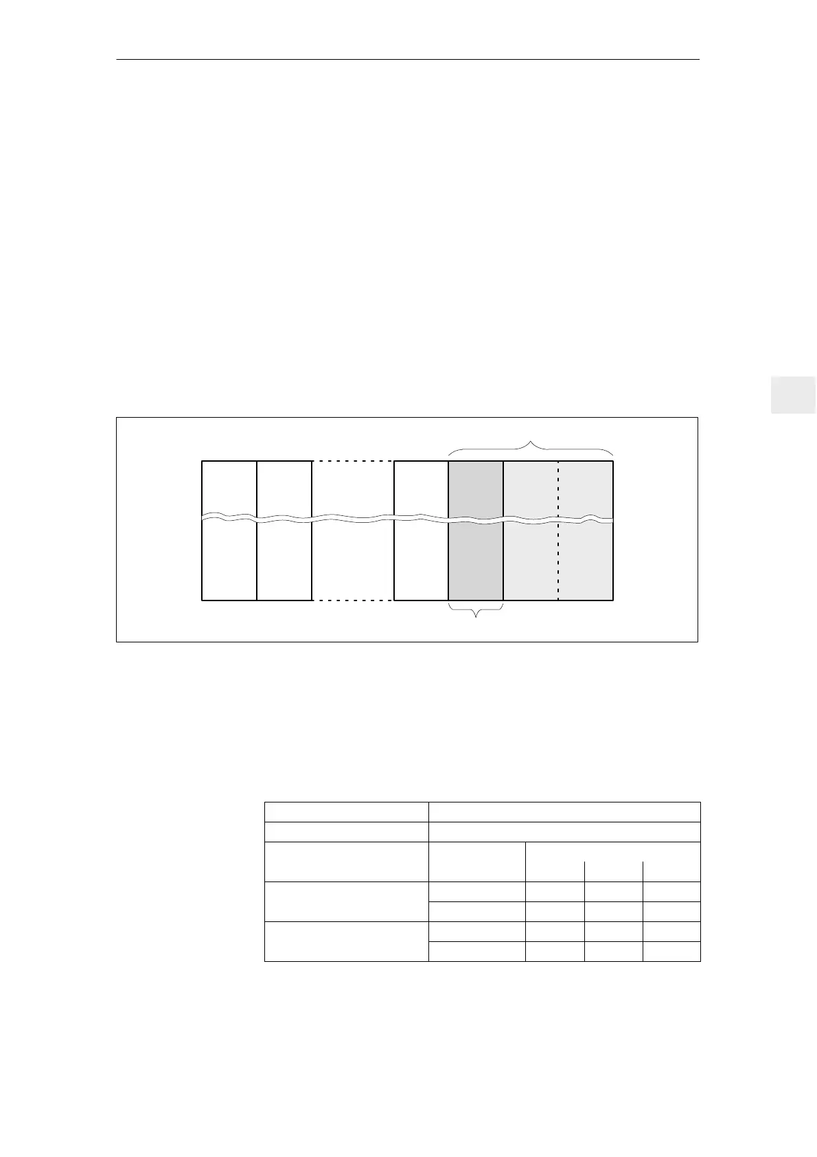
The capacitor module should be preferably located at the righthand end of the
system group. It is connected via the DC link busbar.
I/R LT LT
Module with 4.1 mF (width: 100 mm)
Module with 20 mF (width: 300 mm)
100
Fig. 6-12 Mounting location of the capacitor module
Several capacitor modules can be connected in parallel depending on the line
supply infeed used.
For 4.1 mF capacitor modules, the total charging limits of the line supply infeed
may not be exceeded (refer to Catalog NC 60, Section 10).
Table 6-14 Max. number of capacitor modules
Infeed unit Capacitor modules which can be connected
UI 5 kW None
Monitoring module
without 1 w 2
UI 10 kW
Module 4.1 mF 1 1 1
UI 10 kW
I/R 16 kW
Module 20 mF 3 1 0
UI 28 kW
Module 4.1 mF 4 4 4
UI 28 kW
I/R 36–120 kW
Module 20 mF 3 1 0
Configuring
information
6 Infeed Modules

 Loading...


