9
05.01
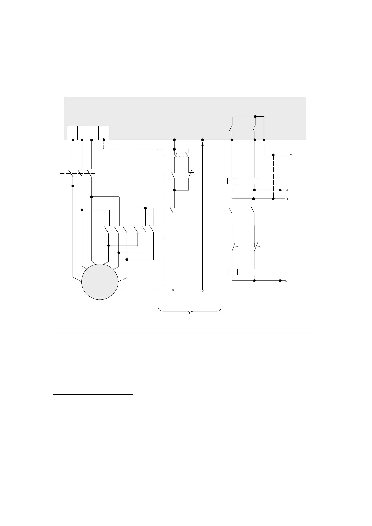
9.10 Star–delta operation
9-286
Siemens AG 2001 All rights reserved
SIMODRIVE 611 Planning Guide (PJU) – 05.01 Edition
Term. An
2)
Term. An
2)
SIMODRIVE 611 analog system MSD module
V2U2
W2
Selectable
relay outputs
2)
Term. 663 Term. 289
PE
K2h
K2
K1
K
x
3)
K2
K1
K1
Y
K1h
1PH
Y/
K1
K2
U2
V1 W1
V2
W2
U2
V2
W2
Y/∆
changeover
Pulse
enable
from NC/PLC
K2hK1h
K2
U1
Auxiliary contactor
power supply
max. 30 V DC
K
x
3)
Term. En
1)
Fig. 9-27 Connection diagram for Y/∆ changeover SIMODRIVE 611 analog
1) One input terminal, which can be selected from terminals E1 to E9.
2) Two relay outputs which can be selected from terminals A11 to A61.
3) Safe standstill is not guaranteed by only opening K1 and K2.Thus, for safety–related reasons, electrical isolation
must be provided by contactor K
x
. This contactor may only be switched in the no–current condition, i.e. pulse
enable must be withdrawn 40 ms before the contactor is opened (de–energized). Refer to Sections 9.4.2 and 9.7.
Circuit example =10.
Connection
diagram for Y/∆
changeover 611
analog system
9 Important Circuit Information

 Loading...


