9
05.01
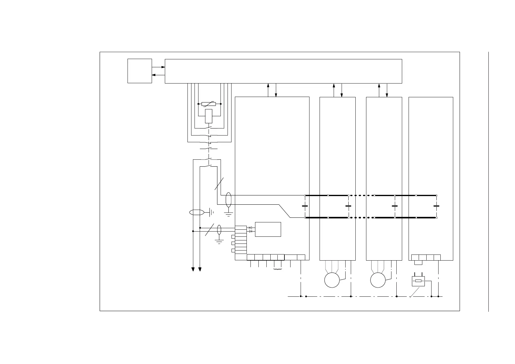
9.12 Operation at power failure
9-298
Siemens AG 2001 All rights reserved
SIMODRIVE 611 Planning Guide (PJU) – 05.01 Edition
M500
P500
2U1
1U1
2V1
1V1
2W1
1W1
X181
U1 V1 1 WL1L2
X131 PE
M600
Drive 1
Drive n
Pulsed
1R 2R 3RPE
P600
C
DCl.
C
DCl.
C
DCl.
Aux. power
supply
Drive 1 Drive n Pulsed resistor
module
NE–module,
M M
Ext. optional pulsed resistor
PE
C
DCl.
U
1 A
44
14
32
22
2
43
21
31
1
43
13
2 A
PLC Drive–related control
Option
Connection to the P500 / M500
monitoring modules
max. 4 units
1. Cable routing according to
EN 60204–1/VDE 0113 Part 1:
Cross–section 1.5 mm
2
(AWG16)
and cable length, max. 3 m
short–circuit proof cable, twisted
and routed e.g. in
metal piping. The cable screens
must be connected to the mounting
panel at both ends through a large
surface area.
2. Contactor 3TC4417–0AB4, 2 pole,
Auxiliary contacts NC+2NO
24 VDC coil voltage;
3TX 7402–3G; Varistor.
The connection
between the power DC link
P600 / M600 and the electronics
auxiliary supply P500 / M500
electrically isolated using contactor
contacts –K1 for the functions
“Open line contactor” and
“Setting–up operation”.
3. Terminals L1 and L2, only available
for I/R modules
80 kW and 120 kW.
3)3)3)
2)
K1
1)
1)
resistor
Fig. 9-31 Circuit example: Operation at power failure
9 Important Circuit Information

 Loading...


