9
05.01
9.12 Operation at power failure
9-300
Siemens AG 2001 All rights reserved
SIMODRIVE 611 Planning Guide (PJU) – 05.01 Edition
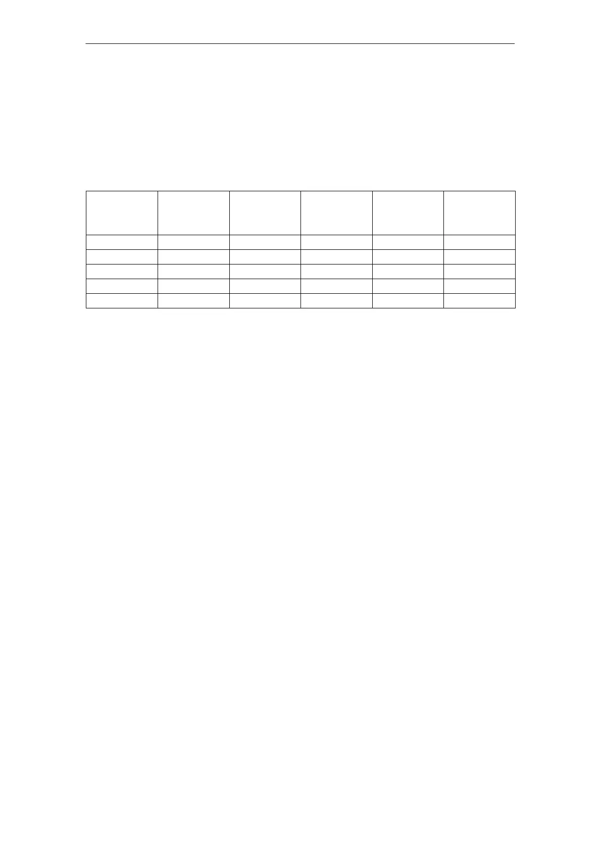
The values for various I/R units are summarized in the following table. In this
case, nominal and minimum capacitances are taken into account. The maxi-
mum possible capacitance (charge limits) comprises the sum of the capaci-
tance of the I/R module and the axis/spindle modules and external supplemen-
tary capacitors (to be provided by the user).The minimum capacitance, used in
table, takes into account a component tolerance of –20% (worst case)
Table 9-3 Nominal and minimum buffer times as a function of various I/R units
Power P
max
of the I/R unit
[kW]
Max. possible
capacitance
C
max
[mF]
Energy contents
(C
max
)
[Ws]
Energy contents
(C
min
)
[Ws]
Buffer time t
n
at
P
max
[ms]
Buffer time t
min
at P
max
[ms]
16 6000 540 432 30.38 24.30
36 20000 1800 1440 45.00 36.00
55 20000 1800 1440 29.46 23.56
80 20000 1800 1440 20.25 16.20
120 20000 1800 1440 13.50 10.80
When engineering emergency retraction, the energy must always be investiga-
ted in order to evaluate whether additional capacitor modules or a generator
axis/spindle is required or not (with approximately dimensioned inertia).
Energy flow
9 Important Circuit Information

 Loading...


