10
05.01
10.1 Installation and connection regulations
10-311
Siemens AG 2001 All rights reserved
SIMODRIVE 611 Planning Guide (PJU) – 05.01 Edition
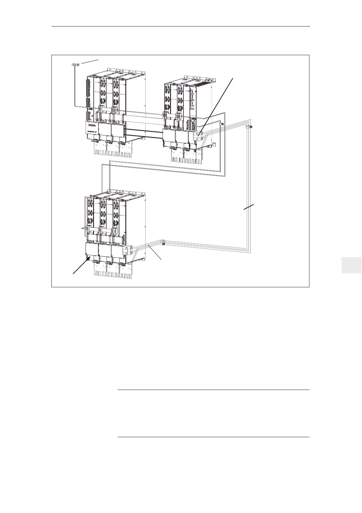
Cable length
max 5 m !
Warning label
Route the PE cable so that it is
close to the P600/M600 conductors
along the mounting panel.
To the NC control
Adapter terminals, order number
for module width 50 – 200 mm
6SN1161–1AA01–0BA0
for module width 300 mm
6SN1161–1AA01–0AA0
Fig. 10-3 Connection example, for a two–tier arrangement
1. The continuous bus cable for a drive group at an input module or monitoring
module may be a max. of 2.1 m (from the supply point).
(from the supply point)
For two–tier arrangements, two equipment bus branches, each max. 2.1 m
long can be used from the branch point at the supply point.
2. The drive bus may be a max. of 11 m.
3. Equipment bus extension, 1500 mm.
Note
Refer to the dimension drawing for connection details of the DC link adapter set
For multi–tier arrangements, a warning label must attached to the first module
of each tier referring to the DC link voltage. The warning information is supplied
on a sheet with the line supply infeed.
Data on the
system arrange-
ment
10 Cabinet Design and EMC

 Loading...


