2 System Configuration
2
05.01
2.8 Line supply connection
2-54
Siemens AG 2001 All rights reserved
SIMODRIVE 611 Planning Guide (PJU) – 05.01 Edition
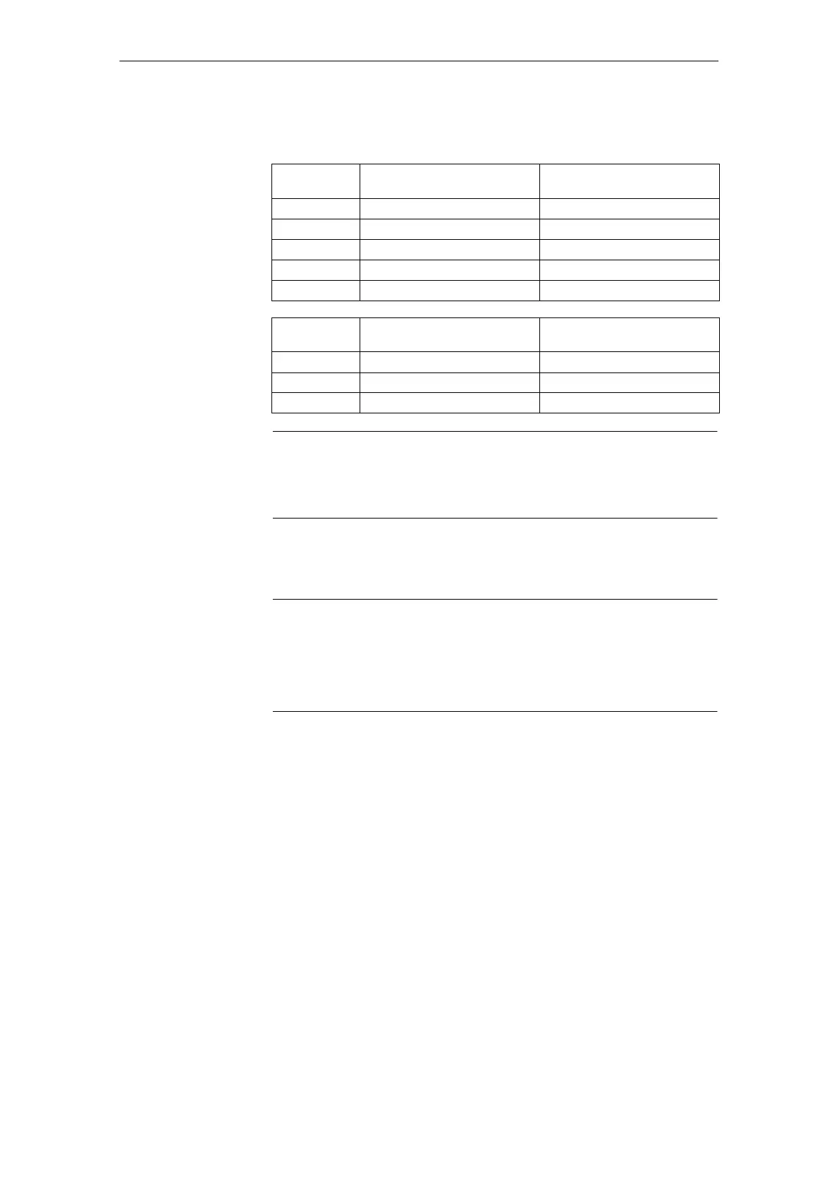
Table 2-4 Engineering information/instructions if you dimension the transformer
yourself
I/R module
used
Required rating Sn of the isola-
ting/autotransformer
Short–circuit voltage
required uk
16/21 kW Sn 21 kVA uk 3%
36/47 kW Sn 46.5 kVA uk 3%
55/71 kW Sn 70.3 kVA uk 3%
80/104 kW Sn 104 kVA uk 3%
120/156 kW Sn 155 kVA uk 3%
UI module
used
Rating Sn required for the iso-
lating/autotransformer
Short–circuit voltage
required uk
5/10 kW Sn 7.8 kVA uk 10%
10/25 kW Sn 14.5 kVA uk 10%
28/50 kW Sn 40.5 kVA uk 10%
Note
Switching elements (main switch, contactors) to switch–in and switch–out the
line filter may have a max. 35 ms delay time between the closing/opening of the
individual main contacts.
It is possible to use an isolating transformer in conjunction with a protective
measure against hazardous currents going through the human body.
Notice
When using an isolating transformer upstream from I/R and UI modules
(module width 100 mm), an overvoltage limiting module should be used,
Order No.: 6SN1111–0AB0V–0AA0; refer to Section 7.
A voltage limiting circuit is included for UE 5 kW, Order No.:
6SN1146–2AB00–0BA1.
If line filters are required and if the rated line supply voltage deviates from the
permissible supply voltage of the line filters (3–ph. 400 V AC or 3–ph. 415 V
AC), then one of the matching transformers, specified in the following, must be
used.
The SIMODRIVE 611 drive converter system is designed for a rated voltage of
300 V phase–grounded neutral point.
This voltage may not be exceeded, as otherwise the drive converter insulation
system could be damaged resulting in inadmissibly high touch voltages.
J
Connection
through an
isolating
transformer

 Loading...


