3
05.01
3.4 Direct position sensing
3-60
Siemens AG 2001 All rights reserved
SIMODRIVE 611 Planning Guide (PJU) – 05.01 Edition
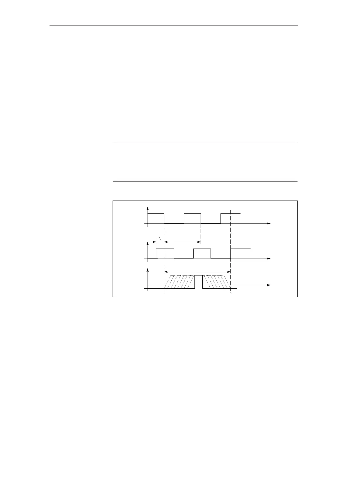
Incremental systems with two squarewave signals A, B, displaced through
90 degrees and a reference mark(s) R SIMODRIVE 611A
Signal transfer: Differential signals
A, *A; B, *B and R, *R
Signal level: acc. to RS422
Supply: 5 V
5 % (also refer to Section
Encoder power supply)
Max. supply current: 300 mA
Max. encoder signal frequency
which can be evaluated: 500 kHz
Note
For the above specified max. encoder signal frequency, the distance between
the signal edges, tracks A and B must be ≥ 200 ns.
Observe the frequency characteristic of the encoder signals!
A–*A
B–*B
R–*R
0
0
0
90_el.
360_ el.
Clear signal range
Fig. 3-4 Signal characteristics for a clockwise direction of rotation
3 Motor Selection, Position/Speed Sensing

 Loading...


