Functions
2.19 Impedance Protection (ANSI 21)
SIPROTEC, 7UM62, Manual
C53000-G1176-C149-7, Release date 03.2010
162
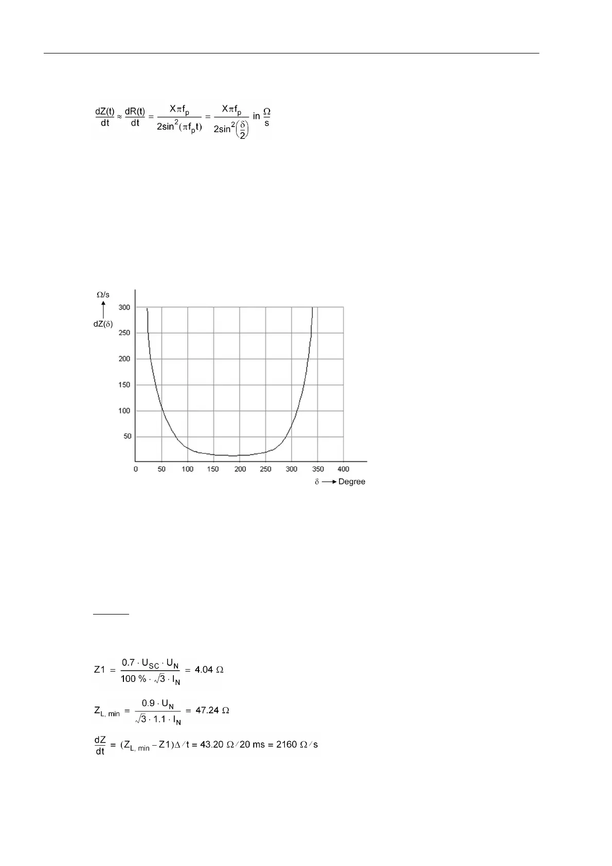
The following relation allows estimation of the rate of change:
Definitions:
X Reactance between the sources of the power swing
f
p
Swing frequency
δ Swing angle
Figure 2-66 shows an example of how the rate of change evolves as a function of the power swing angle. For
an angle of 180° the rate of change is smallest. The further into the power system network (i.e. larger or smaller
angle), the greater the acceleration.
Figure 2-66 Course of the rate of change (f
p
= 1 Hz; X = 10 Ω)
For this reason, the setting value dZ/dt must also be coordinated with the impedance jump occurring at the start
of a short-circuit.
To do so, you determine the minimum operating impedance (ZL, min), form the difference to the setting of the
impedance zone (e.g. Z1) and calculate the impedance gradient, taking into account the one-cycle measuring
interval.
Example
:
U
min
= 0,9 U
N
, I
max
= 1,1 I
N
, u
SC
= 10 %, Δ t = 20 ms
U
N
= 100 V, I
N
= 1 A

 Loading...


