Functions
2.20 Out-of-Step Protection (ANSI 78)
SIPROTEC, 7UM62, Manual
C53000-G1176-C149-7, Release date 03.2010
171
Table 2-11 Transient Machine Reactances (Referred to Secondary Side)
As it may be assumed that the generator is connected with the network via a unit transformer, the setting in the
network direction is chosen such that the out-of-step protection measures with characteristic 1 approximately
70 % to 90 % of the transformer impedance, and with characteristic 2 right into the network. Parametrization of
Zc in address 3506 is set between 70 % and 90 % of the short circuit impedance X
K
of the transformer. For
characteristic 2, in address 3507 Zd - Zc the remaining portion of the transformer short circuit impedance is
set and if necessary complemented by the impedance of the additional line section to be monitored.
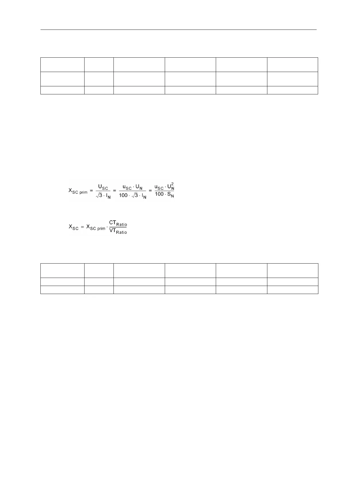
The table below shows typical values of the secondary per unit short circuit impedances X
K
of transformers with
secondary rated currents of I
N
= 1 A and I
N
= 5 A, the following formula shows the calculation of the short circuit
impedance from the short circuit voltage.
Table 2-12 Secondary Per Unit Short Circuit Impedances of Transformers
The setting Z
a
effects the width of the power swing polygon. This setting value 3504 Za is determined by the
total impedance Z
tot
and can be derived from the equation in the figure below. With this for Z
tot
alternately the
sum of the values Z
b
and Z
d
can be used (power swing angle between generator and network) or the sum of
Z
b
and Z
c
(power swing angle between generator and power station unit transformer). The default setting of
address 3504 Za corresponds to the latter case. For simplification, it isassumed that a power swing angle δ =
120° is strived for and since the generator voltage U
G
and the system voltage U
N
are quantatively the same:
Generator Type x
d
'X
d
'
U
N
= 100 V/ I
N
= 1 A
X
d
'
U
N
= 120 V/ I
N
= 1 A
X
d
'
U
N
= 100 V/ I
N
= 5 A
X
d
'
U
N
= 120 V/ I
N
= 5 A
Non-salient pole
rotor
0,13...0,35 7.5 Ω...20.2 Ω 9.4 Ω...24.3 Ω 1.5 Ω...4.0 Ω 1.9 Ω...4.9 Ω
Salient-pole rotor 0,20...0,45 11.5 Ω...26.0 Ω 13.9 Ω...31.2 Ω 2.3 Ω...5.2 Ω 2.8 Ω...6.2 Ω
Transformer type u
SC
X
SC
U
N
= 100 V/ I
N
= 1 A
X
SC
U
N
= 120 V/ I
N
= 1 A
X
SC
U
N
= 100 V/ I
N
= 5 A
X
SC
U
N
= 120 V/ I
N
= 5 A
Unit transformer 8 %...13 % 4.6 Ω...7.5 Ω 5.5 Ω...9.0 Ω 0.9 Ω...1.5 Ω 1.1 Ω...1.8 Ω
General 3 %...16 % 1.7 Ω...9.2 Ω 2.1 Ω...11.1 Ω 0.3 Ω...1.8 Ω 0.4 Ω...2.2 Ω

 Loading...


