Functions
2.20 Out-of-Step Protection (ANSI 78)
SIPROTEC, 7UM62, Manual
C53000-G1176-C149-7, Release date 03.2010
172
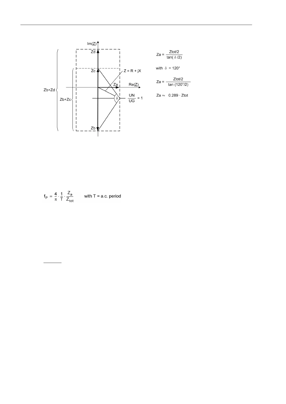
Figure 2-72 Power swing polygon and impedance vectors with angle δ
Maximum power swing frequency
The polygon width Z
a
determines also the maximum detectable power swing frequency. Considering that even
with rapid power swings, at least two impedance values must have been established within the power swing
polygon (which in a limit case differ by the width of the polygon), the following approximative formula can be
used for the maximum detectable power swing frequency f
P
:
At a rated frequency of 50 Hz (i.e. T = 20 ms) the above formula gives:
Z
a
≈ 0.289 · Z
tot
f
P
≈ 10 Hz
as the maximum power swing frequency.
The inclination angle ϕ of the power swing polygon can be set at address 3508 PHI POLYGON and thereby
optimally matched to the particular power system conditions.
Example:
Generator data:
x
d
' = 0,20
U
N
= 6.3 kV
I
N
= 483 A
Transformer data:
u
SC
= 7 %
S
N
= 5.3 MVA
U
N
= 6.3 kV

 Loading...


