Functions
2.24 Overexcitation (Volt/Hertz) Protection (ANSI 24)
SIPROTEC, 7UM62, Manual
C53000-G1176-C149-7, Release date 03.2010
186
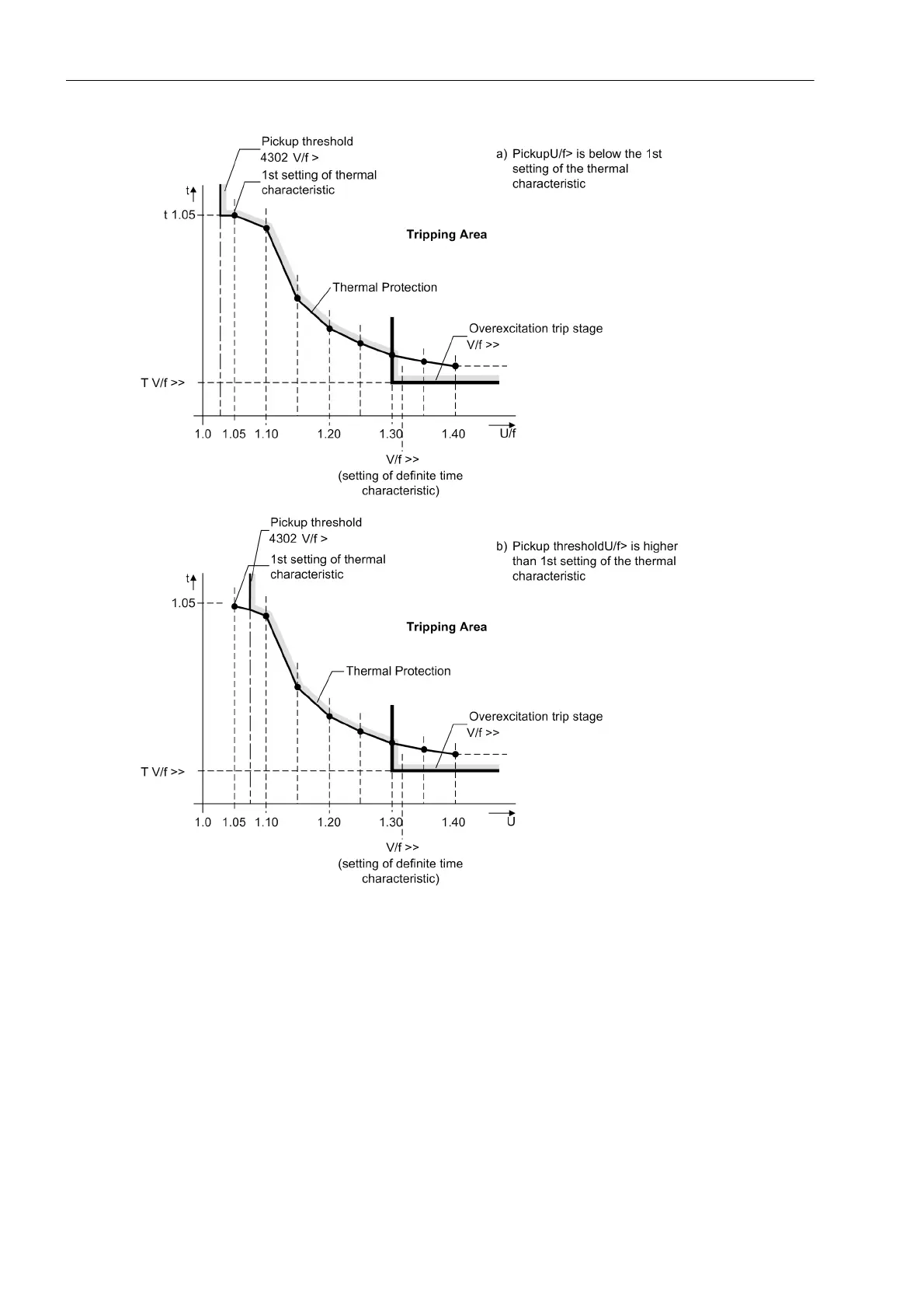
Figure 2-76 Tripping Range of the Overexcitation Protection
The characteristic resulting from the device default settings is shown in the Technical Data Section Overexci-
tation Protection. Figure 2-76 illustrates the behaviour of the protection on the assumption that within the frame-
work of configuration the setting for the pickup threshold (parameter4302 U/f >) was chosen higher or lower
than the first setting value of the thermal characteristic.
The following figure shows the logic diagram for overexcitation protection. The counter can be reset to zero by
means of a blocking input or a reset input.

 Loading...


