Functions
2.33 Interturn Protection (ANSI 59N (IT))
SIPROTEC, 7UM62, Manual
C53000-G1176-C149-7, Release date 03.2010
237
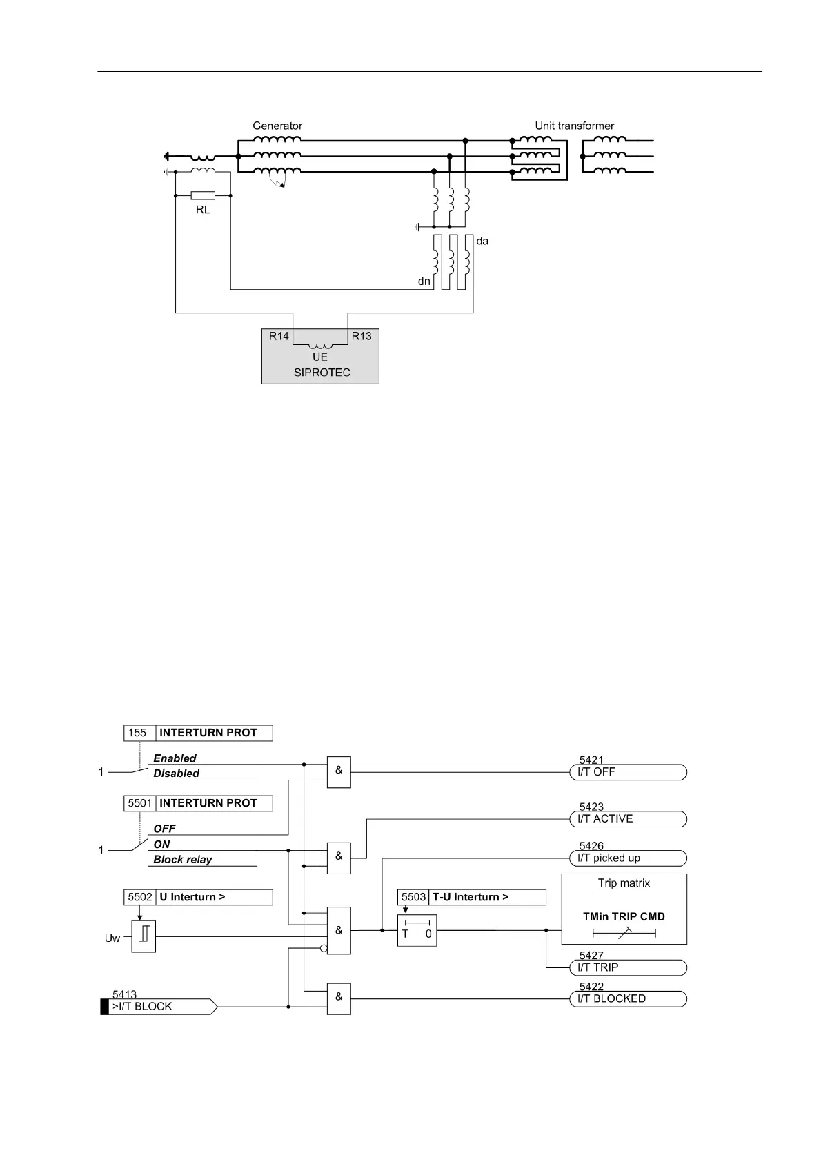
Figure 2-105 Alternative connection of the interturn fault protection
The wide setting range allows the protective function to be used also as single-stage, single-phase overvoltage
protection.
Measurement Method
The U
E
input of the protection is connected as shown in Figure 2-104 or 2-105. An FIR filter determines the
fundamental component of the voltage based on the scanned displacement voltage. Selecting an appropriate
window function has the effect that the sensitivity towards higher-frequency oscillations is decreased and the
disturbing influence of the third harmonic is eliminated while achieving the required measurement sensitivity.
Logic
Figure 2-106 shows the logic diagram. The measured value of the fundamental component is forwarded to the
threshold decision logic. Upon exceeding the threshold, the pickup indication is sent and the timer is started.
The trip command is generated after the time has elapsed.
Figure 2-106 Logic diagram of the interturn fault protection

 Loading...


