Mounting and Commissioning
3.1 Mounting and Connections
SIPROTEC, 7UM62, Manual
C53000-G1176-C149-7, Release date 03.2010
372
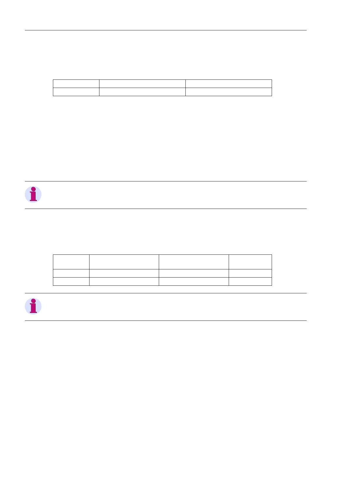
With interface RS232 jumper X111 is needed to activate CTS which enables the communication with the
modem.
Table 3-5 Jumper setting for CTS (flow control) on the C–CPU-2 processor board
1)
Default setting of releases 7UM62..../CC and higher
Jumper setting 2-3: The connection to the modem is usually established with a star coupler or fibre-optic con-
verter. Therefore the modem control signals according to RS232 standard DIN 66020 are not available. Modem
signals are not required since the connection to the SIPROTEC 4 devices is always operated in the half-duplex
mode. Please use the connection cable with order number 7XV5100-4.
Jumper setting 1-2:This setting makes the modem signals available, i. e. for a direct RS232-connection
between the SIPROTEC 4 device and the modem, this setting can be selected optionally. We recommend use
of a standard RS232 modem connection cable (converter 9-pole to 25-pole).
Note
For a direct DIGSI connection to interface RS232 jumper X111 must be plugged in position 2-3.
If there are no external terminating resistors in the system, the last devices on a RS485 bus must be configured
via jumpers X103 and X104.
Table 3-6 Jumper setting of the Terminating Resistors of Interface RS485 on the C-CPU-2 processor
board
Note
Both jumpers must always be plugged in the same way!
Jumper X90 has currently no function. The factory setting is 1-2.
Jumper /CTS from interface RS232 /CTS triggered by /RTS
X111 1-2 2-3
1)
Jumper Terminating resistor
Connected
Terminating resistor
Disconnected
Presetting
X103 2-3 1-2 1-2
X104 2-3 1-2 1-2

 Loading...


