Home
Siemens
Protection Device
SIPROTEC 7UM62
Siemens SIPROTEC 7UM62 User Manual
4
of 1
of 1 rating
638 pages
Give review
Manual
Specs
To Next Page
To Next Page
To Previous Page
To Previous Page
Loading...
Mounting and Commissioning
3.1 Mounting and Connections
SIPROTEC, 7UM62, Manual
C53000-G1176-C149-7, Release date 03.2010
378
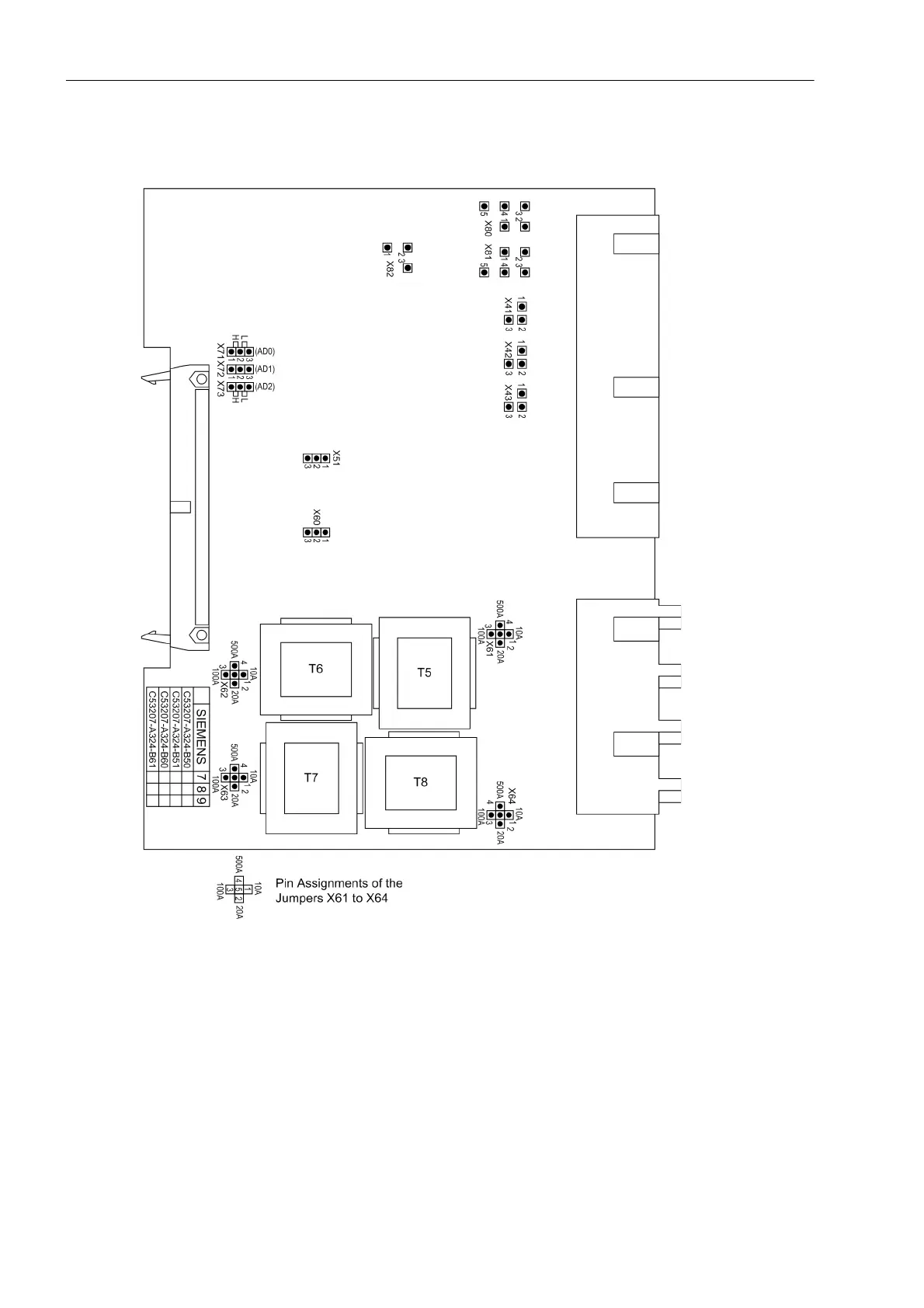
Input/Output Module
C-I/O-2 ( from release 7)
Figure
3-7
C-I/O-2 input/output boar
d rele
ase 7UM62* .../EE or highe
r
,
with represen
tation of jumper
settings required for checking
configuration settings
377
379
Table of Contents
Table of Contents
9
Introduction
21
Overall Operation
22
Application Scope
25
Characteristics
27
Functions
35
Introduction, Reference Power System
37
Function Description
37
Device
39
Setting Notes
39
Settings
40
Information List
41
Ethernet EN100 Modul
42
Function Description
42
Setting Notes
42
Information List
42
Functional Scope
43
Functional Description
43
Setting Notes
44
Settings
48
Power System Data 1
53
Setting Notes
53
Settings
60
Information List
61
Change Group
62
Setting Notes
62
Settings
62
Information List
62
Power System Data 2
63
Function Description
63
Setting Notes
63
Settings
63
Information List
64
Definite-Time Overcurrent Protection (I>, ANSI 50/51) with Undervoltage Seal-In
65
Function Description
65
Setting Notes
66
Settings
68
Information List
68
Definite-Time Overcurrent Protection (I>>, ANSI 50, 51, 67) with Direction Detection
69
Function Description
69
Setting Notes
72
Settings
74
Information List
74
Inverse-Time Overcurrent Protection (ANSI 51V)
75
Function Description
75
Setting Notes
79
Settings
80
Information List
80
Thermal Overload Protection (ANSI 49)
81
Function Description
81
Setting Notes
85
Settings
89
Information List
90
Unbalanced Load (Negative Sequence) Protection (ANSI 46)
91
Function Description
91
Setting Notes
94
Settings
97
Information List
97
Startup Overcurrent Protection (ANSI 51)
98
Function Description
98
Setting Notes
99
Settings
101
Information List
101
Differential Protection and Its Protected Objects
102
Differential Protection (ANSI 87G/87M/87T)
102
Function Description
102
Setting Notes
112
Settings
112
Information List
113
Protected Object Generator or Motor
115
Function Description
115
Setting Notes
116
Protected Object Transformer
118
Function Description
118
Setting Notes
122
Current Transformer Requirements
126
Function Description
126
Earth Current Differential Protection (ANSI 87GN,TN)
128
Function Description
128
Setting Notes
133
Settings
135
Information List
135
Underexcitation (Loss-Of-Field) Protection (ANSI 40)
136
Function Description
136
Setting Notes
139
Settings
143
Information List
144
Reverse Power Protection (ANSI 32R)
145
Functional Description
145
Setting Notes
146
Settings
148
Information List
148
Forward Active Power Supervision (ANSI 32F)
149
Functional Description
149
Setting Notes
150
Settings
151
Information List
151
Impedance Protection (ANSI 21)
152
Functional Description
152
Power Swing Blocking
157
Setting Notes
158
Settings
163
Information List
164
Out-Of-Step Protection (ANSI 78)
165
Measuring Principle
165
Out-Of-Step Protection Logic
167
Setting Notes
169
Settings
174
Information List
174
Undervoltage Protection (ANSI 27)
175
Functional Description
175
Setting Notes
176
Settings
177
Information List
177
Overvoltage Protection (ANSI 59)
178
Functional Description
178
Setting Notes
179
Settings
180
Information List
180
Frequency Protection (ANSI 81)
181
Functional Description
181
Setting Notes
182
Settings
183
Information List
184
Overexcitation (Volt/Hertz) Protection (ANSI 24)
185
Functional Description
185
Setting Notes
187
Settings
189
Information List
189
Inverse-Time Undervoltage Protection (ANSI 27)
190
Function Description
190
Setting Notes
191
Settings
192
Information List
192
Rate-Of-Frequency-Change Protection Df/Dt (ANSI 81R)
193
Function Description
193
Setting Notes
195
Settings
197
Information List
198
Jump of Voltage Vector
199
Functional Description
199
Setting Notes
201
Settings
202
Information List
202
Stator Earth Fault Protection (ANSI 59N, 64G, 67G)
203
Functional Description
203
Setting Notes
208
Settings
210
Information List
210
Sensitive Earth Fault Protection (ANSI 51GN, 64R)
211
Functional Description
211
Setting Notes
213
Settings
214
Information List
214
Stator Earth Fault Protection with 3Rd Harmonics (ANSI 27/59TN 3Rd Harm.)
215
Functional Description
215
Setting Notes
219
Settings
222
Information List
222
Stator Earth Fault Protection with 20 Hz Voltage Injection (ANSI 64G - 100%)
223
Function Description
223
Setting Notes
226
Settings
230
Information List
230
Sensitive Earth Fault Protection B (ANSI 51GN)
231
Function Description
231
Setting Notes
234
Settings
235
Information List
235
Interturn Protection (ANSI 59N (IT))
236
Functional Description
236
Setting Notes
238
Settings
239
Information List
239
Rotor Earth Fault Protection R, Fn (ANSI 64R)
240
Function Description
240
Setting Notes
242
Settings
244
Information List
244
Sensitive Rotor Earth Fault Protection with 1 to 3 Hz Square Wave Voltage Injection (ANSI 64R - 1 to 3 Hz)
245
Function Description
245
Setting Notes
249
Settings
250
Information List
250
Motor Starting Time Supervision (ANSI 48)
251
Functional Description
251
Setting Notes
253
Settings
254
Information List
254
Restart Inhibit for Motors (ANSI 66, 49Rotor)
255
Functional Description
255
Setting Notes
259
Settings
262
Information List
262
Breaker Failure Protection (ANSI 50BF)
263
Function Description
263
Setting Notes
266
Settings
267
Information List
267
Inadvertent Energization (ANSI 50, 27)
268
Functional Description
268
Setting Notes
269
Settings
270
Information List
270
DC Voltage/Current Protection (ANSI 59NDC/51NDC)
271
Functional Description
271
Setting Notes
273
Settings
274
Information List
274
Analog Outputs
275
Function Description
275
Setting Notes
277
Settings
281
Monitoring Functions
282
Measurement Supervision
282
Hardware Monitoring
282
Software Monitoring
284
Monitoring of External Transformer Circuits
285
Setting Notes
287
Settings
287
Information List
288
Supervision
289
Fuse Failure Monitor
289
Malfunction Responses of the Monitoring Functions
291
Setting Notes
293
Settings
293
Information List
294
Trip Circuit Supervision
295
Functional Description
295
Setting Notes
299
Settings
301
Information List
301
Threshold Supervision
302
Functional Description
302
Setting Notes
306
Settings
306
Information List
312
External Trip Functions
313
Functional Description
313
Setting Notes
313
Settings
313
Information List
315
Temperature Detection by Thermoboxes
316
Function Description
316
Setting Notes
317
Settings
319
Information List
324
Phase Rotation
325
Functional Description
325
Setting Notes
326
Protection Function Control
327
Pickup Logic for the Entire Device
327
Function Description
327
Tripping Logic for the Entire Device
328
Functional Description
328
Setting Notes
328
Auxiliary Functions
329
Processing of Annunciation
329
Function Description
329
Statistics
331
Functional Description
331
Information List
332
Measurement (Secondary/Primary/Percentage Values)
333
Functional Description
333
Information List
337
Thermal Measurement
338
Description
338
Information List
339
Diff- and Rest. Measurement
340
Information List
340
Min/Max Measurement Setup
341
Information List
341
Energy
342
Information List
342
Set Points (Measured Values)
343
Information List
343
Set Points (Statistic)
343
Oscillographic Fault Records
344
Function Description
344
Setting Notes
344
Settings
345
Information List
345
Date and Time Stamping
346
Functional Description
346
Commissioning Aids
347
Test Messages to the SCADA Interface During Test Operation
347
Checking the System Interface
347
Checking the Binary Inputs and Outputs
348
Creating a Test Fault Record
348
Command Processing
349
Control Device
349
Description
349
Types of Commands
350
Description
350
Command Processing
351
Description
351
Interlocking
352
Description
352
Command Logging
359
Description
359
Mounting and Commissioning
361
Mounting and Connections
362
Configuration Information
362
Hardware Modifications
365
General
365
Disassembly
367
Switching Elements on the Printed Circuit Boards
370
Interface Modules
383
Reassembly
386
Mounting
386
Panel Flush Mounting
386
Rack and Cubicle Mounting
388
Panel Surface Mounting
389
Checking Connections
390
Checking Data Connections of Interfaces
390
System Interface
391
Termination
391
Analog Output
392
Time Synchronization Interface
392
Optical Fibres
393
Checking the Device Connections
393
Checking System Incorporation
397
Commissioning
400
Test Mode / Transmission Block
401
Testing System Interfaces
401
Checking the Binary Inputs and Outputs
403
Tests for Circuit Breaker Failure Protection
406
Testing Analog Output
406
Testing User-Defined Functions
406
Checking the Rotor Ground Fault Protection at Standstill
407
Checking the 100 % Stator Earth Fault Protection
411
Checking the DC Voltage / DC Current Circuit
414
Trip/Close Tests for the Configured Operating Devices
414
Commissioning Test with the Machine
414
Checking the Current Circuits
419
Checking the Differential Protection
421
Checking the Earth Current Differential Protection
424
Checking the Voltage Circuits
428
Checking the Stator Ground Fault Protection
430
Checking the 100 % Stator Ground Fault Protection
438
Checking the Sensitive Ground Fault Protection as Rotor Ground Fault Protection
439
Checking the Rotor Ground Fault Protection During Operation
440
Checking the Interturn Fault Protection
441
Checks with the Network
443
Creating Oscillographic Fault Recordings for Tests
447
Final Preparation of the Device
449
Technical Data
451
General
453
Analog Inputs/Outputs
453
Auxiliary Voltage
454
Binary Inputs and Outputs
455
Communication Interfaces
457
Electrical Tests
461
Mechanical Stress Tests
462
Climatic Stress Tests
463
Service Conditions
464
Certifications
464
Design
464
Definite-Time Overcurrent Protection (ANSI 50, 51 67)
465
Inverse-Time Overcurrent Protection (ANSI 51V)
466
Thermal Overload Protection (ANSI 49)
471
Unbalanced Load (Negative Sequence) Protection (ANSI 46)
473
Startup Overcurrent Protection (ANSI 51)
475
Differential Protection (ANSI 87G/87M/87T) for Generators and Motors
476
Differential Protection (ANSI 87G/87M/87T) for Transformers
478
Earth Current Differential Protection (ANSI 87GN,TN)
481
Underexcitation (Loss-Of-Field) Protection (ANSI 40)
482
Reverse Power Protection (ANSI 32R)
483
Forward Active Power Supervision (ANSI 32F)
484
Impedance Protection (ANSI 21)
485
Out-Of-Step Protection (ANSI 78)
487
Undervoltage Protection (ANSI 27)
488
Overvoltage Protection (ANSI 59)
490
Frequency Protection (ANSI 81)
491
Overexcitation (Volt/Hertz) Protection (ANSI 24)
492
Rate-Of-Frequency-Change Protection Df/Dt (ANSI 81R)
494
Jump of Voltage Vector
495
Stator Earth Fault Protection (ANSI 59N, 64G, 67G)
496
Sensitive Earth Fault Protection (ANSI 51GN, 64R)
497
Stator Earth Fault Protection with 3Rd Harmonics (ANSI 27/59TN 3Rd Harm.)
498
Stator Earth Fault Protection with 20 Hz Voltage Injection (ANSI 64G - 100%)
499
Sensitive Earth Fault Protection B (ANSI 51GN)
500
Interturn Protection (ANSI 59N (IT))
501
Rotor Earth Fault Protection R, Fn (ANSI 64R)
502
Sensitive Rotor Earth Fault Protection with 1 to 3 Hz Square Wave Voltage Injection (ANSI 64R - 1 to 3 Hz)
504
Motor Starting Time Supervision (ANSI 48)
505
Restart Inhibit for Motors (ANSI 66, 49Rotor)
506
Breaker Failure Protection (ANSI 50BF)
507
Inadvertent Energization (ANSI 50, 27)
508
DC Voltage/Current Protection (ANSI 59NDC/51NDC)
509
Temperature Detection by Thermoboxes
510
Threshold Supervision
511
User-Defined Functions (CFC)
512
Additional Functions
517
Operating Range of the Protection Functions
523
Dimensions
525
Panel Flush and Cubicle Mounting (Housing Size 1 / 2 )
525
Housing for Panel Flush Mounting or Cubicle Mounting (Size )
526
Panel Flush Mounting (Housing Size )
527
Housing for Panel Surface Mounting (Size )
527
Dimensional Drawing of Coupling Device 7XR6100-0CA0 for Panel Flush Mounting
528
Dimensions of Coupling Unit 7XR6100-0BA0 for Panel Surface Mounting
529
Dimensional Drawing of 3PP13
530
Dimensional Drawing of Series Device 7XT7100-0BA00 for Panel Surface Mounting
531
Dimensions of Series Unit 7XT7100-0EA00 for Panel Flash Mounting
532
Dimensional Drawing of Resistor Unit 7XR6004-0CA00 for Panel Surface Mounting or Cubicle Flush Mounting
533
Dimensions of Resistor Unit 7XR6004-0BA00 for Panel Surface Mounting
534
Dimensional Drawing of 20 Hz Generator 7XT3300-0CA00 for Panel Surface Mounting or Cubicle Flush Mounting
535
Maßbild 20 Hz-Generator 7XT3300-0CA00/DD für Schalttafel- oder Schrankeinbau
536
Dimensional Drawing of 20 Hz Generator 7XT3300-0BA00 for Panel Surface Mounting
537
Maßbild 20 Hz-Generator 7XT3300-0BA00/DD für Schalttafelaufbau
538
Dimensional Drawing of 20 Hz Bandpass 7XT3400-0CA00 for Panel Surface Mounting or Cubicle Flush Mounting
539
Dimensional Drawing of 20 Hz Bandpass 7XT3400-0BA00 for Panel Surface Mounting
540
Appendix
541
Ordering Information and Accessories
542
Ordering Information
542
Order Key
542
Accessories
546
Terminal Assignments
549
Panel Flush Mounting or Cubicle Mounting
549
Panel Surface Mounting
551
Connection Examples
553
7UM62 - Connection Examples
553
Connection Examples for RTD Box
561
Schematic Diagram of Accessories
562
Default Settings
565
Leds
565
Binary Input
566
Binary Output
566
Function Keys
567
Default Display
568
Pre-Defined CFC Charts
569
Protocol-Dependent Functions
570
Functional Scope
571
Settings
576
Information List
593
Group Alarms
615
Measured Values
616
Literature
619
Glossary
621
Index
633
4
Based on 1 rating
Ask a question
Give review
Questions and Answers:
Need help?
Do you have a question about the Siemens SIPROTEC 7UM62 and is the answer not in the manual?
Ask a question
Siemens SIPROTEC 7UM62 Specifications
General
Brand
Siemens
Model
SIPROTEC 7UM62
Category
Protection Device
Language
English
Related product manuals
Siemens SIPROTEC 7UM61
94 pages
Siemens SIPROTEC 5 7UM85
92 pages
Siemens SIPROTEC 7UT612
94 pages
Siemens SIPROTEC 7UT63 series
638 pages
Siemens SIPROTEC 7UT613 series
638 pages
SIPROTEC 7UT633*-* N series
638 pages
SIPROTEC 7UT635*-* N series
638 pages
Siemens SIPROTEC 4 7UT6 Series
684 pages
Siemens SIPROTEC 7SJ64
94 pages
Siemens Siprotec 7SD600
170 pages
Siemens siprotec 7SA522
606 pages
Siemens SIPROTEC 4 7VK61
360 pages