Mounting and Commissioning
3.3 Commissioning
SIPROTEC, 7UM62, Manual
C53000-G1176-C149-7, Release date 03.2010
418
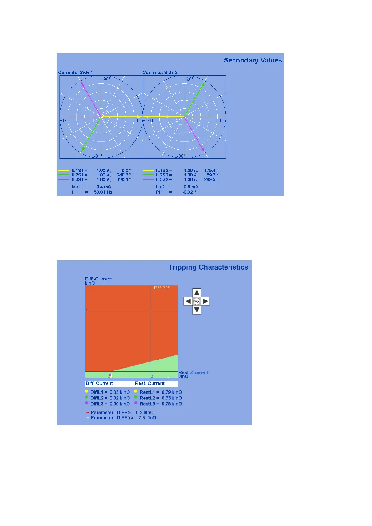
Figure 3-23 Phasor diagram of the secondary measured values — Example
For a test of the differential protection, the differential and restraint currents are entered in the characteristic.
The characteristic shown is a result of the settings for the differential protection. In Figure 3-24, a load current
has been simulated. A small differential current in phase L3 is visible.
Figure 3-24 Differential and Stabilization (Restraint) Currents — Example for Plausible Currents

 Loading...


