Functions
2.10 Inverse-Time Overcurrent Protection (ANSI 51V)
SIPROTEC, 7UM62, Manual
C53000-G1176-C149-7, Release date 03.2010
76
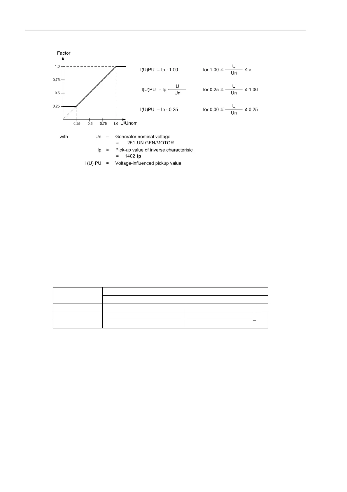
Figure 2-18 Pick-up Value Voltage Dependency
The Ip reference value is decreased proportional to the voltage decrease. Consequently, for a constant current
I, the I/Ip ratio is increased and the trip time is reduced. Compared with the standard characteristics represent-
ed in the „Technical Data“ chapter, the tripping characteristic shifts to the left side in relation to decreasing volt-
age.
The changeover to the lower pick-up value or the reduction of the pickup threshold are performed on a per
phase basis. Allocations of voltages to the current-carrying phases represented in the following table apply. As
the protection used in the generator range is incorporated in the network grading plan, the conversion of the
voltages by the clock transformer must also be considered. Therefore, in principle, a distinction must be made
between a unit connection and a busbar connection which must be communicated to the device by the param-
eter 272 SCHEME. As phase-to-phase voltages are referred to in any case, faulty measurements during earth
faults are avoided.
Table 2-4 Controlling voltages in relation to the fault currents
In order to avoid unwanted operation during a voltage transformer fault, a function blocking is implemented via
a binary input controlled by the voltage transformer protective breaker as well as via the device-internal mea-
suring voltages failure detection ("Fuse-Failure-Monitor", also refer to Section 2.42.1).
The following figure shows the logic diagram of the inverse overcurrent time protection without undervoltage
influencing, whereas Figures 2-20 and 2-21 illustrate the logic diagrams with undervoltage influencing.
Current Voltage
Busbar connection Unit connection
I
L1
U
L1
– U
L2
((U
L1
– U
L2
) – (U
L3
– U
L1
)) / √3
I
L2
U
L2
– U
L3
((U
L2
– U
L3
) – (U
L1
– U
L2
)) / √3
I
L3
U
L3
– U
L1
((U
L3
– U
L1
) – (U
L2
– U
L3
)) / √3

 Loading...


