Functions
2.10 Inverse-Time Overcurrent Protection (ANSI 51V)
SIPROTEC, 7UM62, Manual
C53000-G1176-C149-7, Release date 03.2010
77
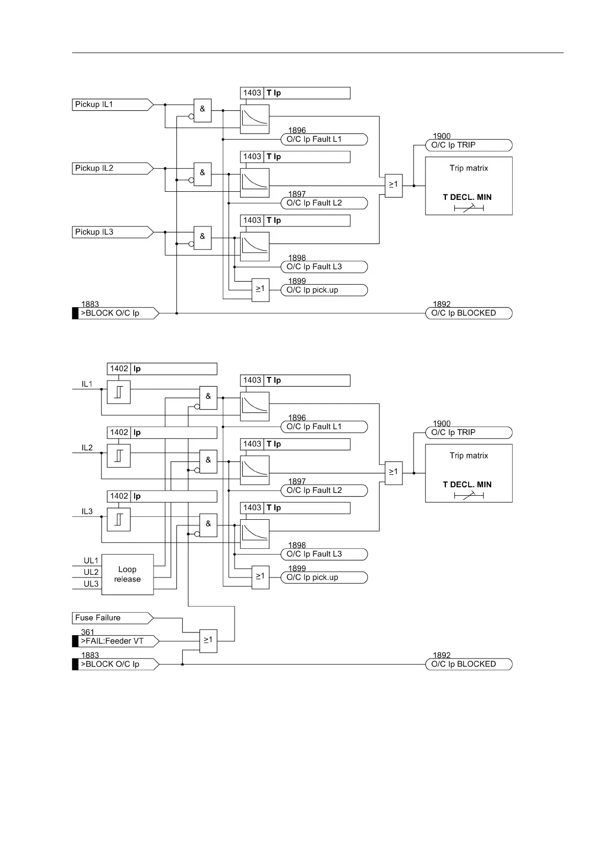
Figure 2-19 Logic Diagram of the Inverse Time Overcurrent Protection without Undervoltage Influencing
Figure 2-20 Logic Diagram of the Voltage Controlled Inverse Time Overcurrent Protection
The changeover to the lower current pickup value on decreasing voltage (loop release) is performed on a phase
by phase basis in accordance with Table 2-4.

 Loading...


