SITRANS TH100/200/300 with DVM LCD or SITRANS TH320/420 with display
You can nd the values of ∆T2G in the tables
Table 11-3 Gas Ex i/nA/ec (Page 133),
Table 11-4 Gas Ex i/nA/ec (Page 134),
Table 11-5 Type 2N (Page 134) and
Table 11-6 Type 2N (Page 135) and
∆T2D in the table Table 11-9 Dust Ex i/tb (Page 137) and
Table 11-10 Type 2N (Page 138).
Table 11-1 Gas hazardous area Zone 1
Permissible
power supply parameters
T
3
= Permissible ambient temperature
Gas hazardous area Zone 1 / Div. 1:
SITRANS TH100/200/300
with DVM LCD
Gas hazardous area Zone 1:
SITRANS TH320/420
with display
U
i
= 30 V DC
I
i
= 120 mA
L
i
= 0 μH
C
i
= 2.2 nF
P
i
= 900 mW
- T4: -40 … +85 °C - ∆T2G
T5: -40 … +65 °C - ∆T2G
T6: -40 … +50 °C - ∆T2G
U
i
= 30 V
I
i
= 100 mA
P
i
= 750 mW
T4: -40 °C ≤ T
3
≤ +75 °C - ∆T2G
T6: -40 °C ≤ T
3
≤ +45 °C - ∆T2G
T4: -40 … +85 °C - ∆T2G
T5: -40 … +70 °C - ∆T2G
T6: -40 … +55 °C - ∆T2G
U
i
= 27 V
I
i
= 90 mA
P
i
= 610 mW
T4: -40 °C ≤ T
3
≤ +85 °C - ∆T2G
T6: -40 °C ≤ T
3
≤ +50 °C - ∆T2G
T4: -40 … +85 °C - ∆T2G
T5: -40 … +75 °C - ∆T2G
T6: -40 … +60 °C - ∆T2G
U
i
= 25.2 V
I
i
= 84 mA
P
i
= 530 mW
T4: -40 °C ≤ T
3
≤ +85 °C - ∆T2G
T6: -40 °C ≤ T
3
≤ +52 °C - ∆T2G
-
Table 11-2 Dust hazardous area Zone 21
Permissible power supply parameters T
3
= Permissible ambient temperature
Gas hazardous area Zone 1 / Div. 1:
SITRANS TH100/200/300
with DVM LCD
Gas hazardous area Zone 1:
SITRANS TH320/420
with display
U
i
= 30 V DC
I
i
= 120 mA
L
i
= 0 μH
C
i
= 2.2 nF
P
i
= 900 mW
- T4: -40 … +85 °C - ∆T2G
T5: -40 … +65 °C - ∆T2G
T6: -40 … +50 °C - ∆T2G
U
i
= 30 V
I
i
= 100 mA
P
i
= 750 mW
T85 °C: -40 °C ≤ T
3
≤ +53 °C - ∆T2D T4: -40 … +85 °C - ∆T2G
T5: -40 … +70 °C - ∆T2G
T6: -40 … +55 °C - ∆T2G
Technical data
11.1 Rated conditions
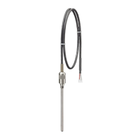
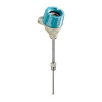
SITRANS TS100/TS200/TS300/TS500/TSinsert/TSthermowell
Operating Instructions, 08/2020, A5E47810090-AA 131