2-15
To add an Input/Output (I/O) card to the 4005, use the following steps:
Note: Refer to the SMPL Programming, Edit SMPL section of Chapter
6 for more information on card addressing and points.
1. Make sure all jumpers and relays are set correctly and install the card in
the Physical Slot desired (refer to Pub. No. FA4-21-700).
After installing the I/O card, apply power to the 4005. An “Extra I/O
Card” trouble occurs. Acknowledge the trouble and continue.
2. Follow Steps 1 through 3 under Editing a Point Label.
3. Press <Next> or <Previous> to scroll through the menus until
[
(GLW&DUG] is displayed (A) and then press <Enter>.
A.
B.
C.
D.
Figure 2-13. Typical Screens Used to Add an Input/Output Card
4. Press <Next> or <Previous> until [$GG,2&DUG] is displayed (B) and
then press <Enter>.
The focus brackets ( [ ] ) appear in the Card Address field (C) of the
display. Refer to Table 2-3 for address information.
18
18
19
19
20
20
21
21
22
22
27
27
26
26
25
25
24
24
23
23
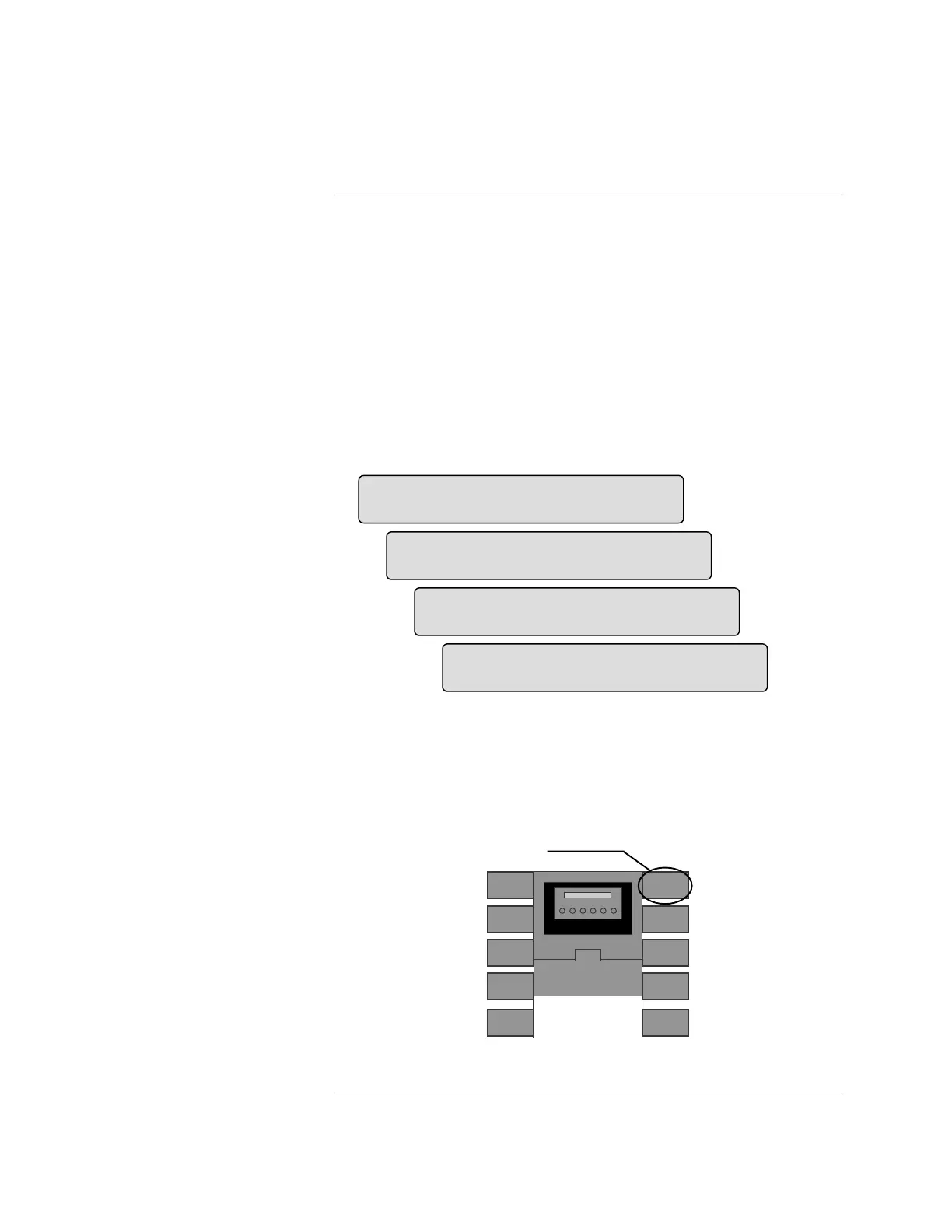
Figure 2-14. I/O Card Address/Locations
Continued on next page
Operations Involving Cards:
Adding an Input/Output (I/O)
Adding an Input/Output (I/O)
Card
),5( 683(59,625< 7528%/(
3URJUDPPLQJ>(GLW&DUG@
),5( 683(59,625< 7528%/(
(GLW&DUG>$GG,2&DUG@
&DUG >@3DQHO6ORW
&DUG7\SH 3RLQW0RQLWRU
&DUG 3DQHO6ORW
&DUG7\SH 3RLQW0RQLWRU
Card Slot #1
Card Slot #2
Card Slot #3
Card Slot #4
Card Slot #5
Card Slot #10
Card Slot #9
Card Slot #8
Card Slot #7
Card Slot #6
Card Addresses
Technical Manuals Online! - http://www.tech-man.com