Chapter 3
Theory of Operation
Focus 30/35 Service Manual 3 - 26 P/N 79000035_SM, Version 1.5
Functional description
A mechanical centre unit holds a glass disc with optical encoder pattern. Two bridges with LED
illumination are mounted on the angle control board in opposite possition over the glass disc. This
diametrical reading provides accuracy of 2”. By using two separate tracks a uniform accuracy and
resolution around the circle is obtained. Both tracks are illuminated with a single laser light source
and projected on a CMOS image area sensor. By using one common sensor for both tracks usual
alignment problems are eliminated. The design will be compact and less parts have to be assembled.
The function of the disc assembly is the same for both horizontal and vertical sensor but the
mechanical axis is different due to how the disc is mounted.
The angle sensor is designed not only for displaying and storing angle data but also to support the
servo system with fast angle information. Final angle data calculations are made in the main control
board MCB.
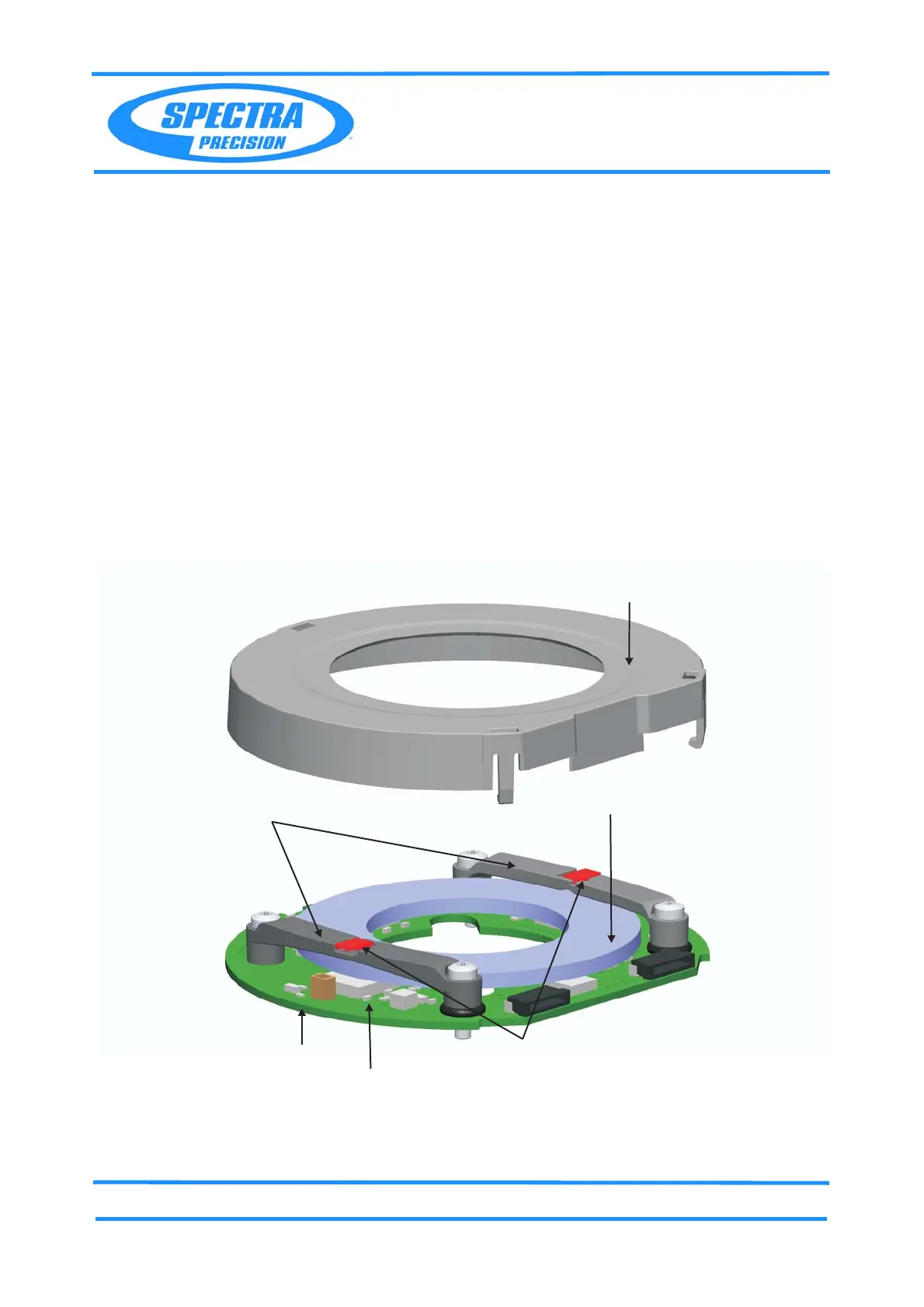
Principle angle sensor
Fig. 3-24 Principle angle sensor
The LED light is transmitted through an encoder glass disc. A pattern from the encoder glass disc is
projected on the detector, a CMOS sensor reads the pattern from the coarse and fine code on the disc.
Glass circle
Angle control board
Illumination bridge
Housing
CMOS image area sensor
LED
 Loading...