Chapter 3
Theory of Operation
Focus 30/35 Service Manual 3 - 28 P/N 79000035_SM, Version 1.5
Block diagram
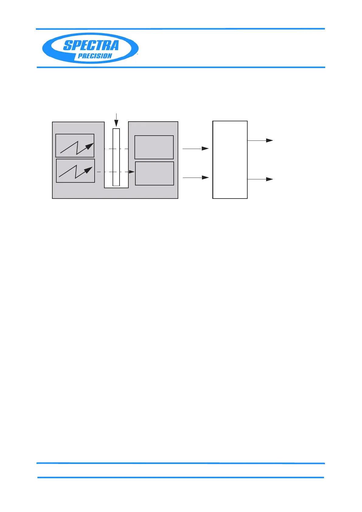
Fig. 3-27 Angle unit block diagram
To make the absolute encoder robust and less sensitive to eccentric mounting errors, two CMOS
sensors are positioned with 180 separation at the disk to read the tracks (coarse and fine code). The
final angle value is calculated as the mean value of these two readings and first order errors with same
size but different signs will be eliminated.
Service
Maintenance
• Self calibration by PASS service software
Replacement of service parts
• Horizontal Base part complete
• Vertical angle disc
• Angle control board
• LED on bridge
CMOS
Sensor
Angle disc
Angle control board
MCB
board
Angles
Display
MotorMotorMMotor drives
LED
LED
Angles
CMOS
Sensor
 Loading...