10B-35 Body Electrical Control System:
Junction block connector “L06”
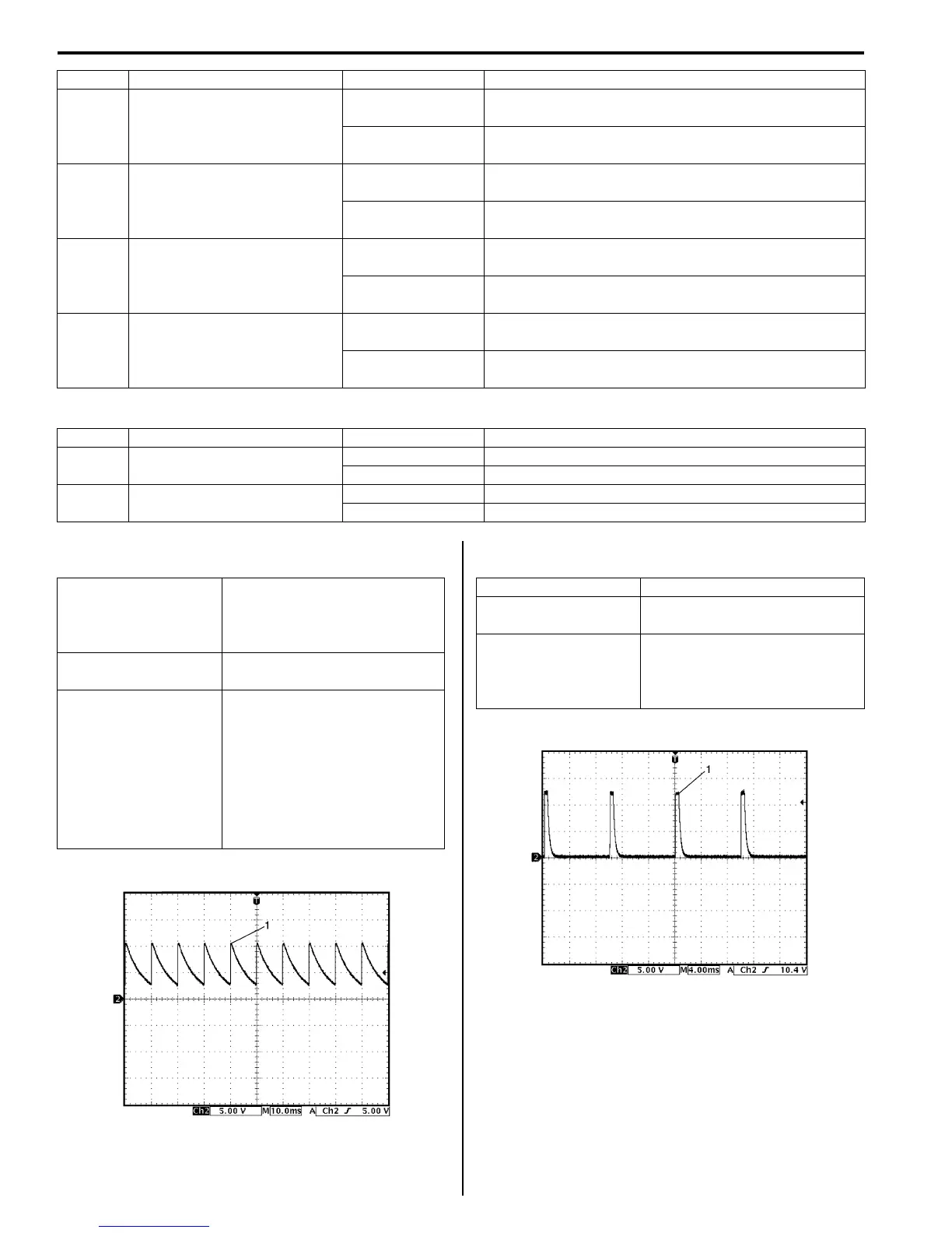
Reference waveform No. 1
Parking brake or brake fluid level switch signal (1)
Reference waveform No. 2
“3” position switch signal (1) for TCM
L05-6
Right side door mirror heater
(if equipped)
10 – 14 V
Engine is running and rear end door window defogger
is in operation
0 V
Engine is running and rear end door window defogger
is not in operation
L05-7
Left side door mirror heater (if
equipped)
10 – 14 V
Engine is running and rear end door window defogger
is in operation
0 V
Engine is running and rear end door window defogger
is not in operation
L05-8
Rear end door window
defogger wire
10 – 14 V
Engine is running and rear end door window defogger
is in operation
0 V
Engine is running and rear end door window defogger
is not in operation
L05-9 Rear wiper control
10 – 14 V
Ignition switch is at ON position and rear wiper is not in
operation
0 V
Ignition switch is at ON position and rear wiper is in
operation
Terminal Circuit Normal voltage Condition
Terminal Circuit Normal voltage Condition
L06-9
Door lock actuator control
(Unlock)
10 – 14 V Unlock signal is output for rear door lock actuator
0 V Unlock signal is not output for rear door lock actuator
L06-10
Door lock actuator control
(Lock)
10 – 14 V Lock signal is output for all door lock actuators
0 V Lock signal is not output for all door lock actuators
Measurement terminal
Parking brake switch
CH2: “L01-6” to “G33-3”
Brake fluid level switch
CH2: “E46-5” to “G33-3”
Oscilloscope setting
CH2: 5 V / DIV
TIME: 10 ms / DIV
Measurement
condition
Parking brake switch:
• Ignition switch is at ON
position, parking brake lever
is released
Brake fluid level switch
• Ignition switch is at ON
position, brake fluid level is in
normal
I4RS0AA20018-02
Measurement terminal CH2: “L01-8” to “G33-3”
Oscilloscope setting
CH2: 5 V/DIV
TIME: 4 ms/DIV
Measurement
condition
Ignition switch is at ON position
and A/T selector lever is at any
position other than “2” or “3”
position
I4RS0AA20015-02
 Loading...


