Body Electrical Control System: 10B-36
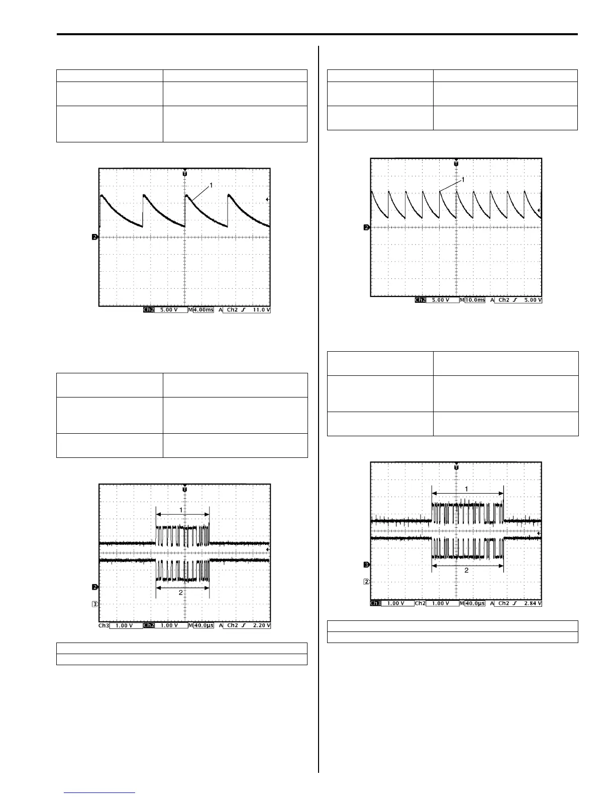
Reference waveform No. 3
Driver side seat belt switch signal (1)
Reference waveform No. 4
BCM – ABS/ESP® control module CAN communication
signal
Reference waveform No. 5
Oil pressure switch signal (1)
Reference waveform No. 6
BCM – DLC CAN communication signal
Measurement terminal CH2: “L01-14” to “G33-3”
Oscilloscope setting
CH2: 5 V/DIV
TIME: 4 ms/DIV
Measurement
condition
Ignition switch is at ON position
and driver side seat belt is
fastened
Measurement terminal
CH2: “E46-1” to “G33-3”
CH3: “E46-2” to “G33-3”
Oscilloscope setting
CH2: 1 V/DIV
CH3: 1 V/DIV
TIME: 40 µs/ DIV
Measurement
condition
Ignition switch is at ON position
1. CAN communication line signal (High)
2. CAN communication line signal (Low)
I4RS0AA20016-02
I4RS0AA20017-02
Measurement terminal CH2: “E46-11” to “G33-3”
Oscilloscope setting
CH2: 5 V / DIV
TIME: 10 ms / DIV
Measurement
condition
Engine is running and oil
pressure is in normal condition
Measurement terminal
CH2: “G37-1” to “G33-3”
CH3: “G37-3” to “G33-3”
Oscilloscope setting
CH2: 1 V / DIV
CH3: 1 V / DIV
TIME: 40 µs / DIV
Measurement
condition
Ignition switch is at ON position
1. CAN communication line signal (High)
2. CAN communication line signal (Low)
I4RS0AA20018-02
I4RS0AA20019-02
 Loading...


