Engine General Information and Diagnosis: 1A-191
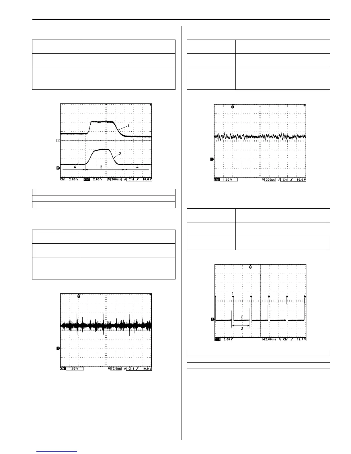
Reference waveform No.24
MAP sensor signal (1) with engine racing
Reference waveform No.25
Knock sensor signal at engine speed 4000 r/min.
Reference waveform No.26
Knock sensor signal at engine speed 4000 r/min.
Reference waveform No.27
Oil control valve signal with engine idling
Measurement
terminal
CH1: “C37-53” to “C37-55”
CH2: “C37-54” to “C37-55”
Oscilloscope
setting
CH1: 2 V/DIV, CH2: 2 V/DIV
TIME: 200 ms/DIV
Measurement
condition
• After warmed up to normal
operating temperature
• Engine racing
2. TP sensor signal
3. Racing
4. Idle
Measurement
terminal
CH1: “C37-56” to “C37-58”
Oscilloscope
setting
CH1: 1 V/DIV
TIME: 10 ms/DIV
Measurement
condition
• After warmed up to normal
operating temperature
• Engine running at 4000 r/min.
I4RS0B110071-01
I4RS0B110072-01
Measurement
terminal
CH1: “C37-56” to “C37-58”
Oscilloscope
setting
CH1: 1 V/DIV
TIME: 200 µs/DIV
Measurement
condition
• After warmed up to normal
operating temperature
• Engine running at 4000 r/min.
Measurement
terminal
CH1: “C37-60” to “C37-59”
Oscilloscope
setting
CH1: 5 V/DIV
TIME: 2 ms/DIV
Measurement
condition
At the moment of the ignition switch
turned on
1. ON signal
2. OFF signal
3. Only duty cycle
I4RS0B110073-01
I4RS0B110074-01
 Loading...


