Engine General Information and Diagnosis: 1A-195
Circuit Description
When the ignition switch is turned ON, the main relay turns ON (the contact point closes) and the main power is
supplied to ECM.
Troubleshooting
NOTE
When measuring circuit voltage, resistance and/or pulse signal at ECM connector, connect the special
tool to ECM and/or the ECM connectors referring to “Inspection of ECM and Its Circuits”.
Step Action Yes No
1 Circuit fuse check
1) Disconnect connectors from ECM with ignition switch
turned OFF.
2) Check for proper connection to ECM connector at “E23-
2”, “E23-29”, “E23-60”, “E23-1”, “E23-16”, “E23-31”,
“C37-58”, “C37-15” and “C37-30” terminals.
3) If OK, check “RADIO” fuse and “IG COIL” fuse for
blowing.
Are “RADIO” fuse and “IG COIL” fuse in good condition?
Go to Step 2. Replace fuse (s) and
check for short in
circuits connected to
fuse(s).
2 Power supply circuit check
1) Measure voltage between “E23-2” terminal of ECM
connector and body ground.
Is voltage 10 – 14 V?
Go to Step 3. “WHT/RED” or “WHT”
wire is open circuit.
3 Ignition signal check
1) Turn ignition switch to ON position.
2) Measure voltage between “E23-29” terminal of ECM
connector and body ground.
Is voltage 10 – 14 V?
Go to Step 4. “BLK/WHT” or “GRN”
wire is open circuit.
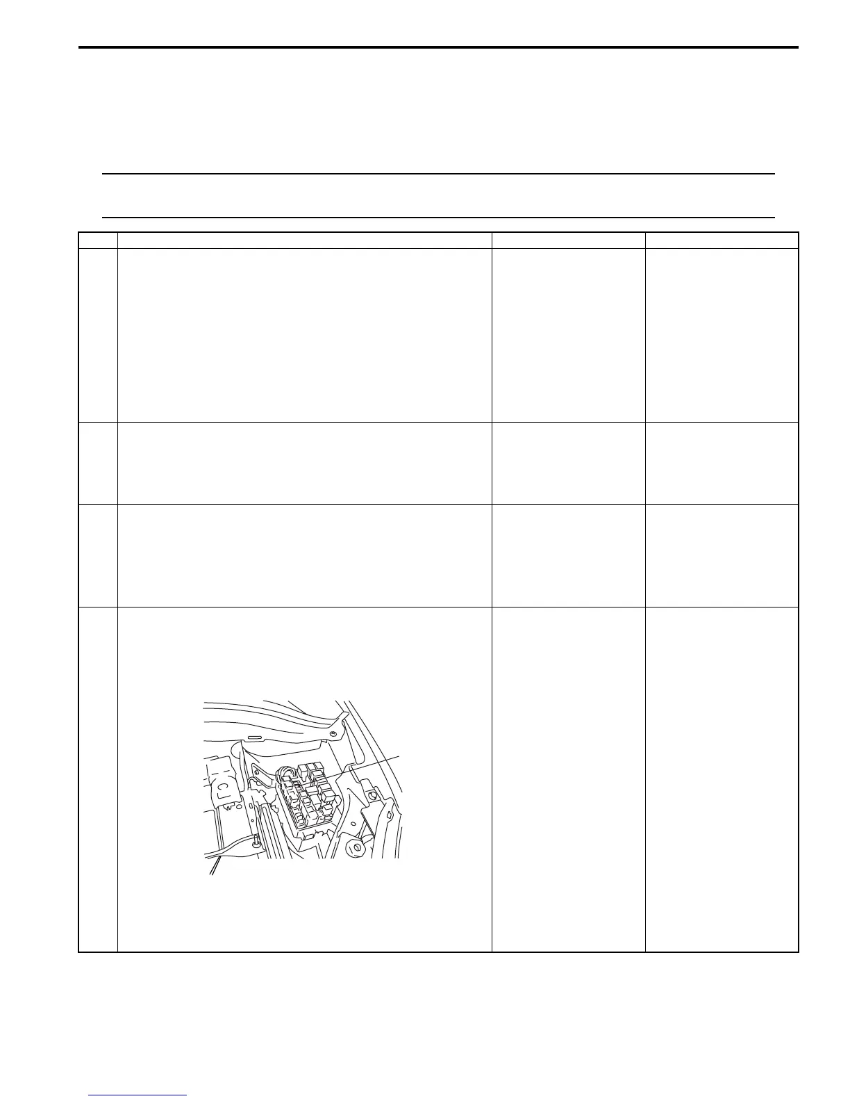
4 Main relay circuit check
1) Turn ignition switch to OFF position.
2) Check “FI” fuse (1) in individual circuit fuse box No.1 for
blowing.
3) If OK, measure voltage between “E23-60” terminal of
ECM connector and body ground.
Is voltage 10 – 14 V?
Go to Step 5. Go to Step 9.
1
I4RS0A110016-01
 Loading...


