1A-196 Engine General Information and Diagnosis:
5 Main relay circuit check
1) Connect connectors to ECM with ignition switch turned
OFF.
2) Turn ignition switch to ON position.
3) Measure voltage between “E23-60” terminal of ECM
connector and body ground.
Is voltage 0 – 1 V?
Go to Step 7. Go to Step 6.
6 ECM ground circuit check
1) Turn ignition switch to OFF position.
2) Disconnect connectors from ECM.
3) Measure resistance between each “E23-31”, “C37-58”,
“C37-15” and “C37-30” terminals of ECM connector and
body ground.
Is resistance 1
Ω
or less?
Substitute a known-
good ECM and recheck.
“BLK/ORN” or “BLK”
wire is open or high
resistance circuit.
7 Main relay circuit check
1) Disconnect connectors from ECM with ignition switch
turned OFF.
2) Using service wire, ground “E23-60” terminal of ECM
connector and measure voltage between each “E23-1”
and “E23-16” terminals of ECM connector and body
ground.
Is voltage 10 – 14 V?
Go to Step 11. Go to Step 8.
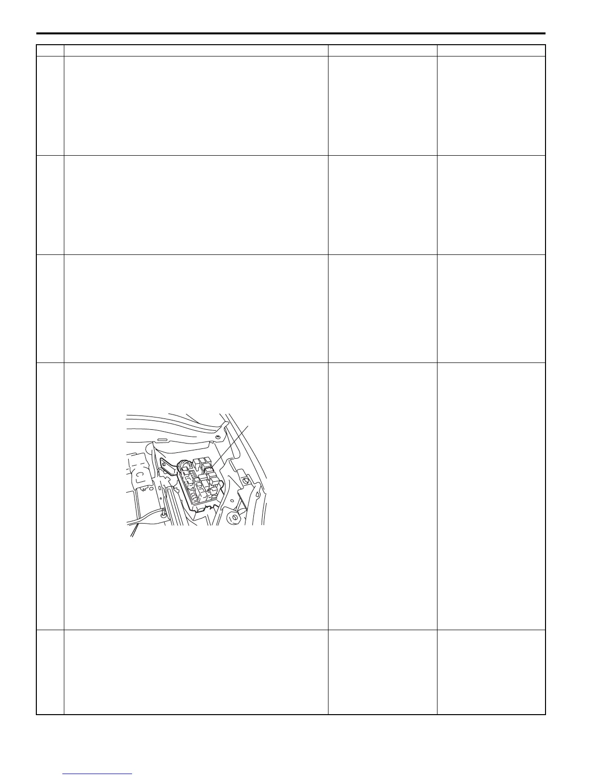
8 Main relay circuit check
1) Remove main relay (1) from individual circuit fuse box
No.1.
2) Check for proper connection to main relay connector at
“BLK/YEL” and “BLK/RED” wire terminals.
3) If OK, measure resistance between each “E23-1” and
“E23-16” wire terminals of ECM connector and “BLK/
RED” wire terminal of main relay connector.
Is resistance 1
Ω
or less?
Go to Step 9. “BLK/RED” wire is open
circuit or high resistance
circuit.
9 Main relay circuit check
1) Remove main relay from individual circuit fuse box No.1
with ignition switch turned OFF.
2) Measure voltage between “BLK/YEL” wire terminal of
main relay connector and body ground.
Is voltage 10 – 14 V?
Go to Step 10. “BLK/YEL” wire is open
circuit.
Step Action Yes No
1
I4RS0A110017-01
 Loading...


