Engine General Information and Diagnosis: 1A-207
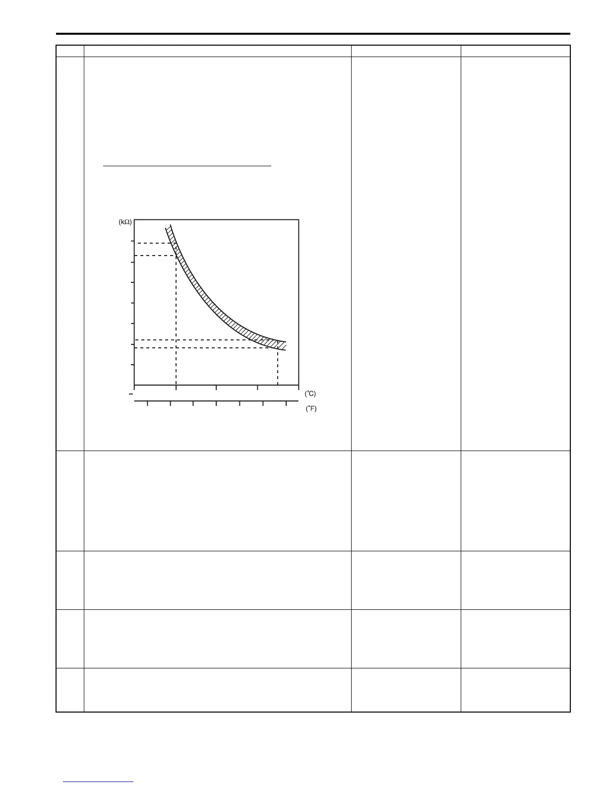
6 A/C evaporator outlet air temp. sensor check
1) Disconnect connectors from ECM with ignition switch
turned OFF.
2) Check for proper connection to “E23-57” and “E23-54”
wire terminals of ECM connector.
3) If OK, measure resistance between “E23-57” and “E23-
54” wire terminals of ECM connector.
Evaporator temp. sensor resistance
At 0 °C: 6.3 – 6.9 kΩ
At 25 °C: 1.8 – 2.2 kΩ
Is resistance within specification?
Go to Step 7. Faulty A/C evaporator
outlet air temp. sensor
or its circuit.
7 DTC check of A/C refrigerant pressure sensor circuit
1) Connect scan tool to DLC with ignition switch turned
OFF.
2) Turn ON ignition switch.
3) Check ECM for DTC of A/C refrigerant pressure sensor
circuit.
Is there DTC P0532 or DTC P0533?
Go to applicable DTC
diag. flow.
Go to Step 8.
8 A/C refrigerant pressure sensor voltage check
1) Check A/C refrigerant pressure sensor voltage referring
to “Inspection of ECM and Its Circuits”.
Is voltage within specified value?
Go to Step 9. Check amount of
refrigerant. If OK,
replace A/C refrigerant
pressure sensor.
9 Radiator cooling fan check
1) Check radiator cooling fan referring to “Radiator Cooling
Fan Motor On-Vehicle Inspection in Section 1F”.
Is check result satisfactory?
Radiator cooling fan
drive circuit malfunction.
If circuit is OK, go to
Step 6.
Replace radiator cooling
fan motor.
10 A/C compressor control system check
Is A/C compressor started when A/C and blower speed
selector switch are turned ON with engine running?
A/C system is in good
condition.
Go to Step 11.
Step Action Yes No
7
6
5
4
3
2
1
10
20 30
40
50
0
10
20 30
60 70
80
Resistance
Temperature
I3RB0A110053-01
 Loading...


