Automatic Transmission/Transaxle: 5A-83
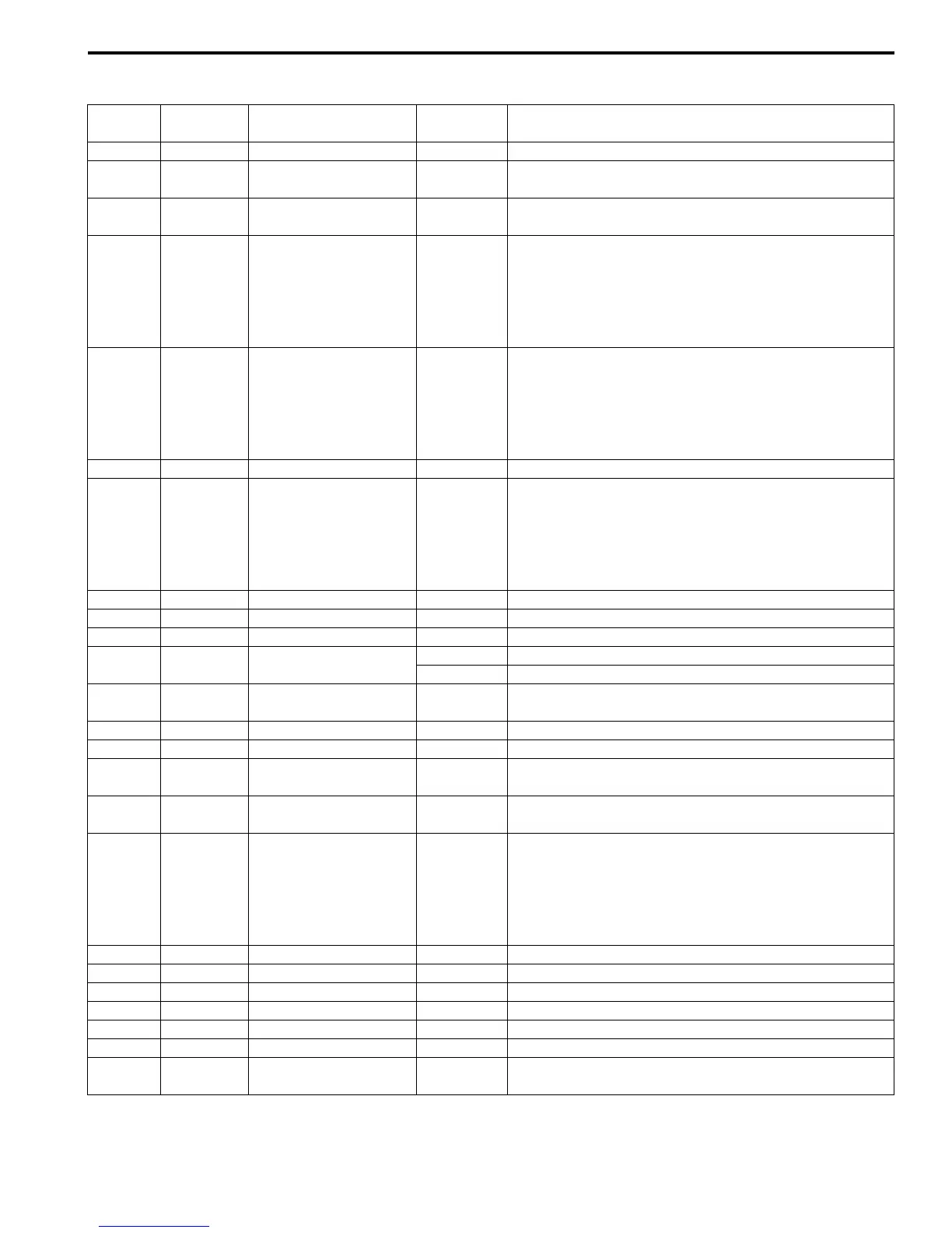
Connector “C34”
Terminal Wire color Circuit
Standard
voltage
Condition
1 BLK Ground 0 – 1 V Ignition switch ON
2
LT GRN/
BLK
Pressure control
solenoid valve (–)
0.6 – 1.0 V Ignition switch ON
3WHT/BLK
TCC pressure control
solenoid valve (–)
0.6 – 1.0 V Ignition switch ON
4GRY
Pressure control
solenoid valve (+)
*0 – 0.6 V
↑↓
10 – 14 V
(“Reference
waveform
No. 1: ”)
Engine running at idling.
(Output signal is duty pulse. Duty ratio varies
depending on throttle valve opening.)
5WHT/BLU
TCC pressure control
solenoid valve (+)
*0 – 0.6 V
↑↓
10 – 14 V
(“Reference
waveform
No. 2: ”)
Engine running at idling.
(Output signal is duty pulse. Duty ratio varies
depending on torque converter clutch operating
condition.)
6 YEL/BLK Power source 10 – 14 V Ignition switch ON
7WHT
CAN communication
line (Low)
*2.5 – 3.6 V
↑↓
1.6 – 2.5 V
(“Reference
waveform
No. 3: ”)
Engine running at idling with after warming up.
(CAN communication signal is pulse. Pulse signal
frequency varies depending on engine condition.))
8— — — —
9— — — —
10 — — — —
11 LT GRN
Transmission fluid
temperature sensor (+)
2.9 – 3.1 V Ignition switch ON, fluid temperature is 20 °C (68 °F)
0.3 – 0.5 V Ignition switch ON, fluid temperature is 100 °C (212 °F)
12 ORN
Transmission fluid
temperature sensor (–)
0 – 1 V Ignition switch ON
13 — — — —
14 BLU/BLK Timing solenoid valve 0 – 1 V Ignition switch ON
15 BLK/YEL
Shift solenoid valve-B
(No.2)
9 – 14 V Ignition switch ON, select lever in “P” range
16 BRN
Shift solenoid valve-A
(No.1)
9 – 14 V Ignition switch ON, select lever in “P” range
17 RED
CAN communication
line (High)
*2.5 – 3.6 V
↑↓
1.6 – 2.5 V
(“Reference
waveform
No. 3: ”)
Engine running at idling with after warming up.
(CAN communication signal is pulse. Pulse signal
frequency varies depending on engine condition.)
18 — — — —
19 — — — —
20 — — — —
21 — — — —
22 — — — —
23 BLK Ground 0 – 1 V Ignition switch ON
24 WHT/RED
Power source for back-
up
10 – 14 V Constantly
 Loading...


