Automatic Transmission/Transaxle: 5A-85
Reference waveform No. 1
Pressure control solenoid valve signal at engine idling.
Reference waveform No. 2
TCC pressure control solenoid valve signal at engine
idling.
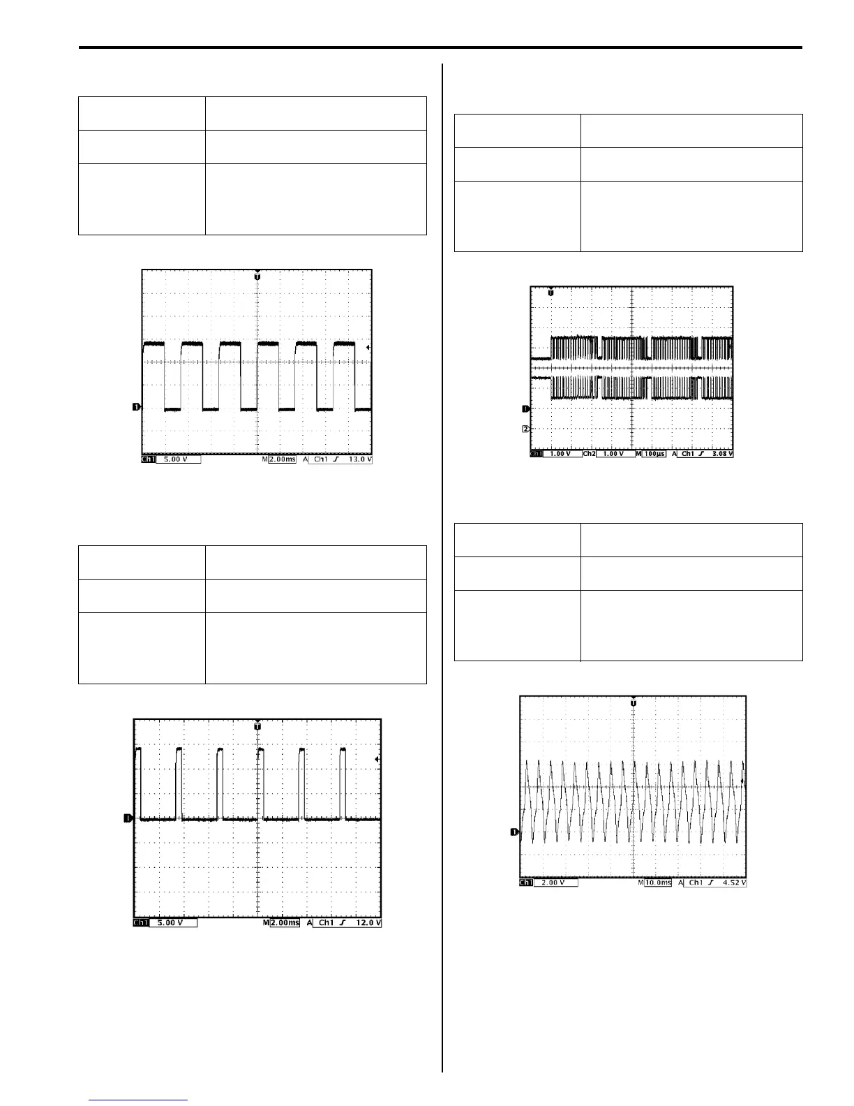
Reference waveform No. 3
CAN communication line (High & Low) signal at engine
idling.
Reference waveform No. 4
Input shaft speed sensor signal at engine idling.
Measurement
terminal
CH1: “C34-4” to “C34-1”
Oscilloscope
setting
CH1: 5 V/DIV
TIME: 20 ms/DIV
Measurement
condition
• After warmed up to normal
operating temperature
• Engine at specified idle speed
with “P” range.
Measurement
terminal
CH1: “C34-5” to “C34-1”
Oscilloscope
setting
CH1: 5 V/DIV
Time: 2 ms/DIV
Measurement
condition
• After warmed up to normal
operating temperature
• Engine at specified idle speed
with “P” range
I3RM0B510029-01
I4RS0A510024-01
Measurement
terminal
CH1: “C34-7” to “C34-1”
CH2: “C34-17” to “C34-1”
Oscilloscope
setting
CH1: 1 V/DIV
TIME: 100 µs/DIV
Measurement
condition
• After warmed up to normal
operating temperature
• Engine at specified idle speed
with “P” range.
Measurement
terminal
CH1: “C35-6” to “C34-1”
Oscilloscope
setting
CH1: 2 V/DIV
TIME: 10 ms/DIV
Measurement
condition
• After warmed up to normal
operating temperature
• Engine at specified idle speed
with “P” range.
I3RM0B510030-01
I3RM0B510027-01
 Loading...


