SVAN 948 USER MANUAL .
3 - 4
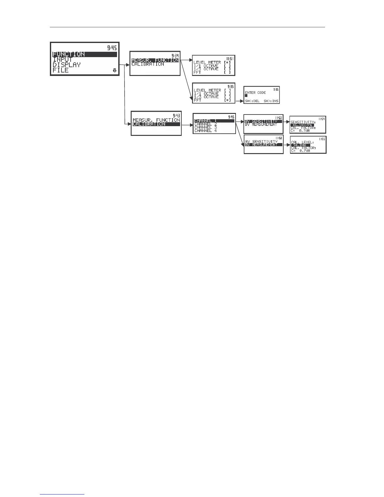
Control diagram of the FUNCTION list
v INPUT (one of the main lists available after pressing the <MENU> push-button)
MEASURE SETUP (sub-list)
§ START DELAY (position); available values of the delay before starting the execution of the
measurements: 1s .. 60s
§ INT. TIME (position); available values of the integration time: 1s .. 24h
§ REP. CYCLE (position); available values for the measurement cycles which has to be
repeated: Inf, 1 .. 1000
§ BUF. STEP (position); available values of the step with which the measurement results are
saved in an instrument’s buffer: 2ms .. 1h
CHANNELS SETUP (sub-list)
§ CHANNEL x (sub-list)
• MODE (x) (position); available types of the channel’s mode used in the first channel
during the measurements:
o VIBR. - in the case of vibration measurements and
o SOUND - in the case of sound measurements
• RANGE (position); available range of the measurements, the user can select the range:
o 17.8m/s
2
or 316m/s
2
in the case of vibration measurements and
o 105dB or 130dB in the case of sound analysis
• FILTER (position); available types of the digital weighting filter used in the first channel
during the measurements
o HP1, HP3, HP10, Vel1, Vel3, Vel10, VelMF, Dil1, Dil3, Dil10, W–Bxy, W–Bz, H–A,
W–Bc, KB, Wk, Wd, Wc, Wj - in the case of vibration measurements and
o LIN, A, C - in the case of sound measurements
• DETECT. (position); available values of the detector time constant used in the first
channel:
o 100ms, 125ms, 200ms, 500ms, 1.0s, 2.0s, 5.0s, 10.0s - in the case of vibration
measurements and
o IMP., FAST, SLOW - in the case of sound measurements