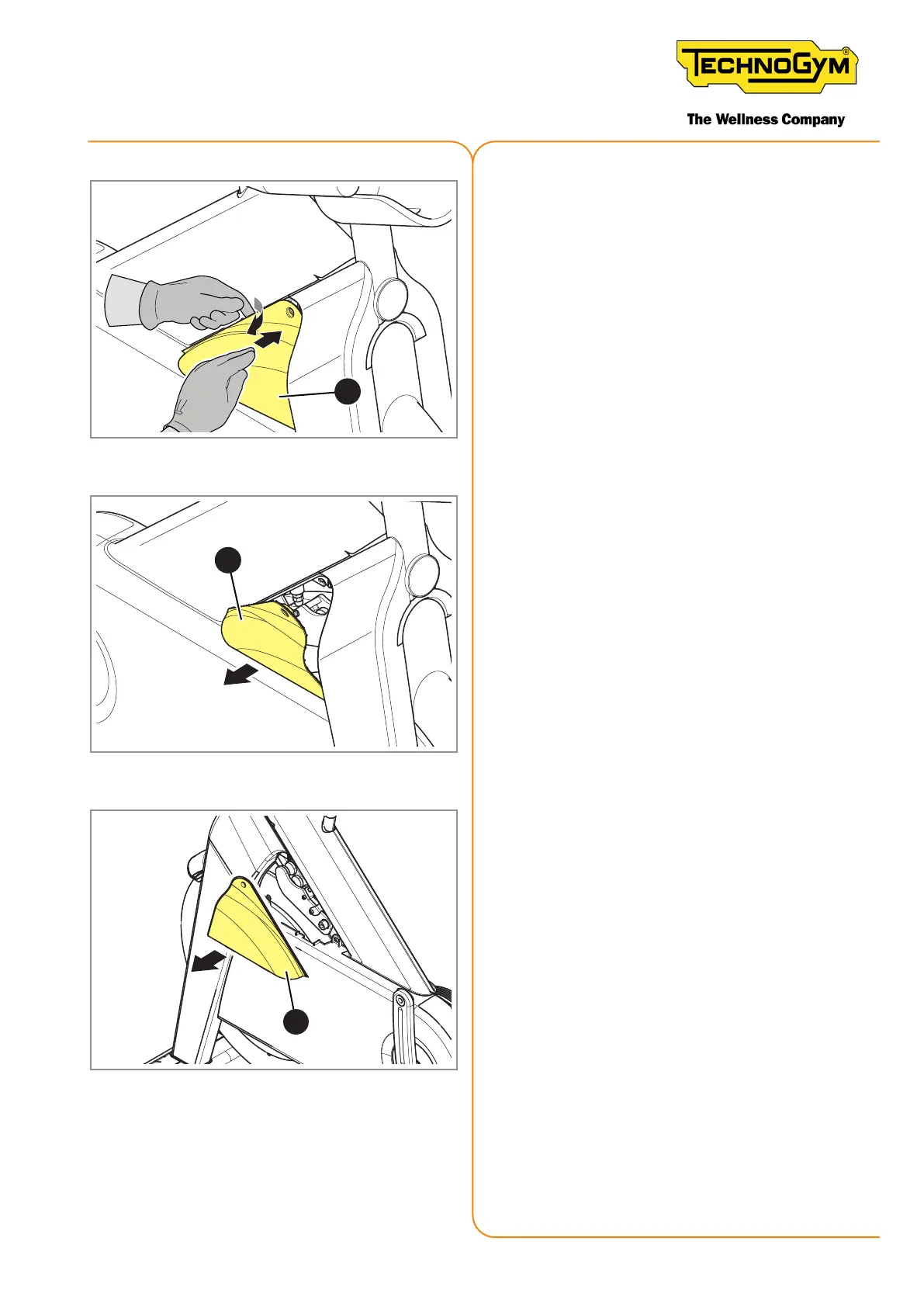
Figure 124
3. Insert a nger from the side and use it as
a lever to lift the guard (2).
Figure 125
4. Remove the guard (2).
3
Figure 126
5. Remove the left brake guard (3) follow-
ing the same procedure used for the right
brake guard.
Totthebrakeguardsbackonthebike,followthe
aforementioned procedure in the reverse order.
New Group Cycle (D92):
Technical Service Guide - Rev. 5.1
Document uncontrolled when printed
Page 143